Create a Dynamic Compaction Plan with Quality Targets
Use the Create Dynamic Compaction command to create a plan of dynamic compaction drop locations based on an origin, orientation, and specified spacing (rows and columns). You can then export the plan for cranes running DPS900 in the field.
The area in which drop locations are created is based on 'region logic' (in this case, the intersection of sections and inclusion areas within a project boundary, and excluding an exclusion area. Drop locations can be individually deleted, but cannot be moved or copied. If the plan is rebuilt after changes are made, any drop locations that were deleted may reappear and will need to be manually deleted.
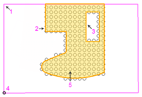
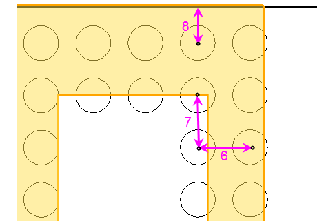
Figure: Parts of a Dynamic Compaction Plan
- Section boundary
- Inclusion boundary
- Exclusion area
- Origin point of the grid of drop locations
- Orientation of the grid
- Column spacing
- Row spacing
- Edge tolerance
Prerequisites:
- Licensed module; See the Subscription Plans page. For a license matrix by command, see the License page in the TBC Community. Also see View and manage licensed features.
To access the command:
- Select Create Dynamic Compaction Plan in Drill Pile Compact > Dynamic Compaction.
- Right-click Dynamic Compaction in the Project Explorer and select Create Dynamic Compaction Plan.
To create a dynamic compaction plan:
- In the Name box, pick an object in a graphic view to use its name or type a unique identifier for the compaction plan as you want it to appear in the Project Explorer and to the DPS900 operator.
Note: If the plan name includes a number, that number will be auto incremented (e.g., Plan 1 Drops auto-increments to Plan 2 Drops). If the name does not include a number, a number will be appended to the end, and that number will auto-increment. No two dynamic compaction plans can use the same name.
- In the Default layer for drop locations list, select the layer on which the drop locations will reside, or select <<New Layer>> to create a new layer for them.
- Click Edit Settings to specify the layout and quality targets for the plan. See Specify Dynamic Compaction Plan Settings for details.
- From the Section boundary box, move your cursor into the Plan View and pick the section boundary within which the compaction will be done.
Note:. Section boundaries have special properties and a heavier line weight by default. When you select the boundary, it is shaded in the Plan View to help you see which region will contain the drop locations. Only section boundaries can be selected here. If the boundary you are trying to choose is not a section boundary, you can change its type in the Properties pane.
- From the Inclusion boundary box, and pick a closed line within which the drop locations will be constrained. Some of the area within the inclusion boundary must overlap the area within the section boundary.
- If there are places within the inclusion area that you do not want to compact, pick them from the Exclusion areas box (hold [Control] while clicking to pick more than one).
- In the Plan View, pick an origin point or type a coordinate in the Origin point box to specify the location/drop location from which the grid will emanate.
Tip: If you are creating multiple plans in adjacent sections, you likely want to specify the same origin point for each plan so that plans created in different sections will align with each other. Duplicate drop location objects can be created at the same location.
- In the Orientation box, specify the angle of the grid of drop locations, which is the direction along a column. Zero is north and positive rotation angles are clockwise (if using the default of North Azimuth in Project Settings > Unit > Azimuth).
Note: If desired, click the
 icon to toggle the auto-advance mode on. When the icon looks like this
  , the origin and/or orientation you entered will be held and this box will be skipped for additional objects.
Tip: You can toggle the Auto-advance mode on/off by pressing [Control] + [.] (period or decimal point). - If you want to create multiple plans, click Apply to create the dynamic compaction plan. The focus returns to the Section boundary box, and the drop locations created by the plan settings appear in graphic views and the Project Explorer. Drop locations are set to an elevation of 0.0.
- Repeat steps 4 - 9.
- Click OK or Close when you are done. When a plan is created, the total area to be dynamically compacted and the number of planned drop locations associated with the plan are reported.
Dependencies:
- Drop locations are dependent upon their parent plan, but not vice versa. If you delete a plan, all of the drop locations are removed, but you can delete individual drop locations without affecting the plan (besides its drop location count and other metrics).
