Unit Settings
Use unit settings to review and change project units, entry formats, and display formats for:
- Coordinates
- Distances
- Angles and vertical angles
- Azimuths and bearings
- Pressure (atmospheric)
- Temperature
- Velocity
- GPS time (specifically, not GNSS time)
- Stationing
- Areas and volumes
- Mass and weight
- Energy
- Roughness
Notes:
- The current distance units are always shown on the Status Bar. You can also click the units label there to open Project Settings for units.
- Settings for new job sites are inherited from these and other Project Settings. If these settings are not recognized by the assigned controllers, the Unsupported Project Settings dialog displays. You must resolve unsupported job site settings before creating a job site.
To access the settings:
- Select Project Settings in the Quick Access Toolbar.
The Project Settings dialog displays.
- Click Units in the left pane.
Entering units
When you edit unit format settings, you are changing how the units display in views, spreadsheets, and commands. You can, however, enter units in any of the valid display formats that you see in the format settings. These are converted to the display format for the unit. For additional details, see Calculate and Enter Values.
Converting units
If your project units are set to one type, such as International foot, you can still enter other types of units by including a character for the type. For example, you can enter 3m to specify 3 meters. The unit you enter is converted to the project units.
Caution! If you change the units of your project, it will be recomputed when you click . It is recommended that you exit Project Settings immediately after changing units, before changing other project settings.
|
Unit Settings |
|
| Undefined value |
Enter the character or word to display in a unit control when the value has not yet been defined. What you enter here will display as the default in many boxes when you run commands. |
|
Coordinate |
|
| Display order |
Select the order in which you want to import, enter, and display coordinates. See Enter a Coordinate for additional entry options. These settings are essential when you use coordinate controls, import point files, create points and coordinates, specify local site settings, and create planar surfaces. |
| Relative |
Enter the character or word that you want to use to indicate that a coordinate you are entering is relative to the last coordinate and not absolute. Examples of how a relative character can be used to place the next coordinate 20 units away along the x axis and 40 units along the y axis from the current location:
|
| Expand horizontal standard errors |
Yes - Select this to display horizontal standard errors as northing and easting coordinates (when available). No - Select this to display horizontal standard errors as a single root mean square (RMS) value. |
| Mirror elevations |
For marine and other applications, select this to specify that elevations below zero/sea level be displayed and plotted as positive numbers. Conversely, elevations above zero will be displayed as negative numbers. |
| Decimal precision |
Select decimal precision levels for latitude/longitude, coordinate, and elevation values. Then opt whether to display trailing zeros and decimals. Examples for a coordinate elevation of 21.0301:
Examples for a coordinate elevation of 10.000
|
| Suffix |
Select whether to add a unit suffix (m or ft) to a displayed coordinate. If Yes, select whether to add a space between the coordinate and the suffix. Note: In some commands and reports, this setting is overridden by a contextually-logical default. |
| Latitude/longitude |
Select a degree or decimal degree format in which to display latitudes and longitudes, and whether to include a directional label and zero minutes and seconds. Examples:
|
|
Distance |
|
| Unit |
Select whether to work in feet or meters. If feet, specify whether they are US survey feet or International feet. See Enter a Distance for additional entry options.
These settings are essential when you use distance controls, import georeferenced images, import planar surfaces, and offset lines. |
| Formatting |
For Decimal precision, Trailing zeros, and Trailing decimal, see above. For Rounding mode, specify whether to round numbers, and if so, whether to round them up or down to the nearest whole number. Examples for rounding a line length of 5.20051:
For Automatic rounding, select Yes to use the previously set decimal precision. Select No to manually specify a decimal precision in the Round to nearest list. The rounding method will be used in either case. |
| Suffix |
Select whether to include a unit suffix (m or ft) after each displayed distance value. If Yes, select the Abbreviation for the suffix and whether to add a space between the unit and the suffix. Note: In some commands and reports, this setting is overridden by a contextually-logical default. |
| Alternate |
Optionally, select an alternate unit to display for distances in certain reports, commands, and graphic displays. For example, in addition to displaying distance in meters, you can select to display the distance in feet or chains: "711.884 m (2335.573 ft)" or "146.423 m (7.279 ch)." Read-only alternate distance units can be displayed in the single- and double-proportioning commands and reports, labels, label tables, measurement commands, parcel and linestring properties, scale bars, and the Map Check report. Also, select the unit abbreviation and decimal precision to display for the alternate unit. |
|
Angular |
|
| Unit |
Select whether you want to enter and display angular units in degrees, grads, or radians (or a sub-unit of any):
These settings are essential when you use angle controls. |
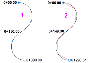
| Chord Length |
Specify the default chord length to use for chord-defined arcs and spirals, such as those used when creating alignments for railroads.
Figure: Arc- versus chord-defined stationing |
| Formatting |
See Formatting above. |
| Suffix |
See Suffix above. |
| Degrees, minutes, seconds |
If you selected degrees, minutes, seconds as the angular unit type, select the format and rounding mode described in Formatting above. |
|
Azimuth |
|
| Unit |
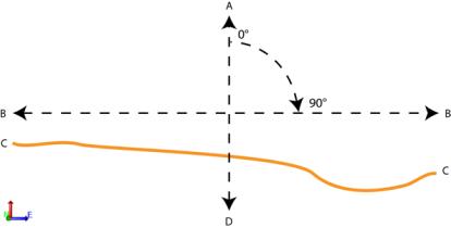
Select whether you want to enter and display horizontal angles in North azimuth, South azimuth, or Bearing format. See Enter an Angle for additional entry options. If you select Bearing, the Bearing settings below become available.
Figure: Azimuth angles
A. North azimuth system B. South azimuth system Figure: North azimuth and south azimuth These settings are essential when you use angle controls. |
| Formatting |
Specify whether to include an indication of the azimuth type (NA, SA, etc.) after displayed azimuth values. See Enter a Bearing for additional azimuth type abbreviations. Note: In some commands and reports, this setting is overridden by a contextually-logical default. |
| Suffix |
Select whether to include a suffix after each displayed azimuth unit. If Yes, select whether to add a space between the unit and the suffix. |
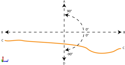
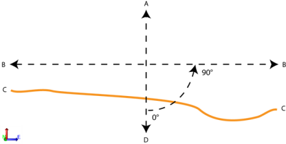
| Bearing settings |
These settings are only available and applicable if you select Bearing for the azimuth Unit above. Select whether to Always show north or Always show south bearings. Then select a bearing format. Note: Selecting Yes for one setting will select No for the other. If you select No for both settings, the displayed bearing defaults to showing from north. Examples for a 90° bearing:
Figure: Bearings |
| Degrees, minutes, seconds |
See Degrees, minutes, seconds above. |
|
Vertical angle |
|
| Unit |
Select whether you want to enter and display vertical angles in Zenith angle, Horizon angle, Nadir angle, Vertical distance, Percent slope, or Slope ratioformat.
A - Zenith (the direction opposite of the nadir) B - Horizon C - Existing ground D - Nadir (determined by a plumb line) Figure: Zenith angle
Figure: Horizon angle
Figure: Nadir angle Select whether to display a slope ratio as Run to rise (horizontal distance followed by vertical distance; 20:1) or Rise to run (vertical distance followed by horizontal distance; 1:20). Also, select the limit at which a slope equal or greater will be displayed as a slope ratio instead of percent slope in reports and graphic views. These settings are essential when you use vertical angle controls, or create a surface tie. |
| Formatting |
Select whether to include an indicator of the vertical angle type (Z, H, N, etc.) after each displayed vertical angle unit. |
| Decimal precision |
Select the decimal precision to use when vertical angles are shown as angles, ratios, percents or distances. |
| Suffix |
See Suffix above. |
| Degrees, minutes, seconds |
See Degrees, minutes, seconds above. |
|
Pressure |
|
| Unit |
Select the unit type to use for atmospheric pressure values displayed in the Propertiespane for total stations. |
| Formatting |
Select how you want to format the atmospheric pressure value. |
| Suffix |
Select whether to display the atmospheric pressure unit abbreviation after the unit value and whether to include a space before the abbreviation (for example, 1013.2 mb (hPa)). |
|
Temperature |
|
| Unit |
Select the unit type to use for temperature values displayed in the Propertiespane for total stations. |
| Formatting |
Select how you want to format the temperature value. |
| Suffix |
Select whether to display the temperature unit abbreviation after the unit value and whether to include a space before the abbreviation (for example, 8.9 C). |
|
Velocity |
|
| Unit |
Select the unit type to use for ground velocity values of compactors (or other machines) as displayed in machine data overlays. |
| Formatting |
Select how you want to format the velocity value. |
| Suffix |
Select whether to display the velocity unit abbreviation after the unit value and whether to include a space before the abbreviation. |
| Alternate |
Optionally, select an alternate velocity unit to display in certain reports, commands, and graphic displays. For example, you can select to display the velocity in km/hour, miles/hour, or knots. Also, select the unit abbreviation and decimal precision to display for the alternate unit. |
|
GPS time |
|
| Display Time Offset |
Select a format to use to display GPS-related time (for example, in occupation and vector Property panes and the Time-Based View tab).
Note: Other general references to time zone in Trimble Business Center come from your operating system: Start > Control Panel > Clock, Language, and Region > Date and Time. |
|
Station |
|
| Formatting |
Select the format in which you want to enter and display stations and station equations. If you select the User Interval option in the Station format box, enter the distance that is represented by a stationing of 1+00 in the Station interval box. For example: A distance of 50 meters will display a station of 1+00 at 50 meters along the alignment and a station of 2+00 at a station of 100m along the alignment. These settings are essential when you use station controls, create and edit horizontal alignments, enter station equations, label horizontal alignments and run corridor reports. |
| Suffix |
See Suffix above. |
|
Area |
|
| Unit |
Select whether to work in feet, yards, or meters. |
| Formatting |
See Formatting above. |
| Suffix |
Select whether to display the area unit abbreviation after the unit value and whether to include a space before the abbreviation (for example, 120 m²). |
| Alternate |
Select an alternate unit (acres or hectares) in which to report calculated areas. This setting is used when you run an Earthwork Report on a surface area within a boundary. The alternate units are shown in parentheses after your project units. Example:
|
|
Volume |
|
| Unit |
Select whether to work in cubic feet, yards, or meters (or acre feet). |
| Formatting |
See Formatting above. |
| Suffix |
Select whether to display the volume unit abbreviation after the unit value and whether to include a space before the abbreviation (for example, 120 m³). |
|
Mass - Weight |
|
|
Unit |
Select the unit type to use for weight values of dynamic compaction tools as displayed in as-built drop location properties. |
|
Formatting |
See Formatting above. |
|
Suffix |
See Suffix above. |
|
Energy |
|
|
Unit |
Select the unit type to use for energy for dynamic compaction drops. |
|
Formatting |
See Formatting above. |
|
Suffix |
See Suffix above. |
|
Roughness Index |
|
|
Unit |
Select the distance unit type to use for road segments analyzed in roughness index reports. |
|
Formatting |
See Formatting above. |
|
Suffix |
See Suffix above. |