Create and Edit a Planar Surface
Use the Create Planar Surface command to create these types of simple, sloping or level planar surfaces:
|
Design type |
Description |
|---|---|
| Constant elevation
(level surface design) |
Single plane with a constant elevation and no slope. Defines a level surface at the specified elevation. |
| Point and direction
(sloping surface design) |
Two intersecting planes with constant cross slopes projecting outward from either side of a line that is formed from a specified point, elevation, and direction. Outward projecting planes are then defined on both sides of this line by their respective cross slopes. Note that the two cross slopes can be designated so as to create a single plane. |
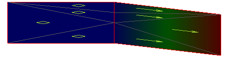
| Two point
(sloping surface design) |
Two intersecting planes with constant cross slopes projecting outward from either side of a line that is formed between two specified points (shown below). Outward projecting planes are then defined on both sides of this line by their respective cross slopes. Once again, the two cross slopes can be designated so as to create a single plane. |
Note: The Constant elevation surface design type is always a level plane at a specified elevation, and it is the simplest way to define such a plane. Therefore, the other two design types will normally be employed only when designing a sloping plane, or two sloping planes that intersect along a central line. In concept, these planes extend outward infinitely. However, in practice, they are implemented within large but finite outer edges.
Once created, planar surfaces appear in graphic views and in the Project Explorer. Planar surface properties are displayed in the Properties pane, where they can be edited.
Planar surfaces can be exported to GCS machines as design files (.tsd) for grade control; they are used to provide guidance similar to that provided by a dual slope laser level (sloping surface) or a level laser (level surface). This guidance is useful when cutting building pads, sports fields, or parking lots. On GCS machines, the planar surfaces are referred to as either Sloping surface or Level surface, depending on their type.
Prerequisites:
- None
To access the command:
- Select Create Planar Surface in Surfaces > Create.
|
Options |
|
|---|---|
| Description |
Use this to include details about the purpose of the surface. The description appears in the Properties pane when you select the surface. |
| Boundary |
Select a closed line (boundary, polyline, or linestring) as the extents of the planar surface. This is particularly helpful for the Constant elevation surface, which is infinite. |
| Elevation/slope type |
Select one of the types described below. The type determines the options displayed in the pane. |
|
Elevation/slope type |
|
| Constant elevation
(Level, planar surface design) Select this when you need a flat plane. Although it is a infinite surface, surface edge lines are drawn for this type at dimensions of 14.5 million m². |
|
|
|
Elevation - Specify the absolute, constant elevation of the plane. |
| Point and direction
(Typically, a sloping surface design) Select this to create a plane or two intersecting planes on either side of a dividing line, with a constant slope along that line, formed in a specified direction, as well as optionally specified cross slopes projecting laterally from both sides of the line. By default, this surface type is created 2000 m². |
|
| Origin Point |
Point - Pick a location in the Plan View or enter the coordinate of the origin point, as defined in your project settings (e.g., easting, northing). Elevation - Enter the elevation of the surface's origin point. |
| Defining Line |
Direction - Pick a location in the Plan View, or enter the direction of the defining line, as defined in your project settings (e.g., dddmmss). Grade - Enter the grade of the defining line in percent slope (measured from the horizontal, positive up, and negative down). |
| Cross Slope |
Left - Enter the cross slope to the left of the defining line (looking away from the origin) in percentage.Right - Enter the cross slope to the right of the defining line in percentage.Note: By specifying the same slope magnitude, but opposite slope directions on both sides, the resulting surface will represent a single plane, sloping at the specified grade of the defining line. |
| Two point
(Typically, a sloping surface design) Select this to create a plane or two intersecting planes on either side of a dividing line, as formed between two coordinate values, as well as optionally specified cross slopes projecting laterally from both sides of that line. By default, this surface type is created 2000 m². |
|
| Origin Point |
Point - Pick a location in the Plan View, or enter the coordinate of the origin point (as defined in your project settings). Elevation -Enter the elevation of the surface's origin point. |
| Second Point |
Point -Pick a location in the Plan View, or enter the coordinate of the second point, as defined in your project settings (e.g., easting, northing).Elevation -Enter the elevation of the surface's second point. |
| Cross Slope |
Left - Enter the cross slope to the left of the defining line (looking away from the origin) in percentage. Right -Enter the cross slope to the right of the defining line in percentage.Note: By specifying the same slope magnitude, but opposite slope directions on both sides, the resulting surface will represent a single plane, sloping at the specified grade of the defining line. |
To Edit a Planar Surface:
Note: Unlike generalized surfaces, you cannot edit anything but the properties of planar surfaces created using this command.
- Select the planar surface in a graphic view or the Project Explorer, right-click and select Properties from the context menu.
- In the Properties pane, click in an available box, and make changes as necessary.
Note: Changes are saved and the surface is updated when you move out of the edited property.
- Click Close.
Dependencies:
- None
