Label an Alignment
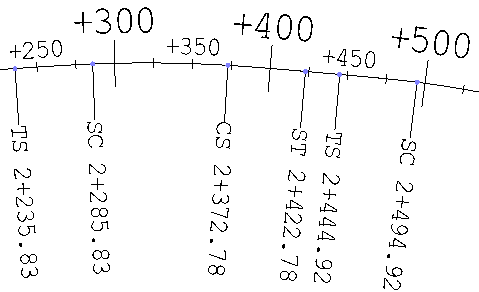
Use the Create Horizontal Alignment Labels command to display values for stations, station equations, horizontal alignment (HAL) points, and abbreviations for other key points along an alignment. These values will be included in output when you print views that show them.
Prerequisites:
- Licensed module; See the Subscription Plans page. For a license matrix by command, see the License page in the TBC Community. Also see View and manage licensed features.
- horizontal alignment
To access the command:
Do one of the following:
- Select Create Horizontal Alignment Label in Corridors > Alignment.
- Right-click an alignment and select Edit Alignment Labels.
To label an alignment:
- Select the horizontal alignment that you want to label in the Alignment list.
- Click the Label Settings button.
- In the Label Settings dialog, specify settings for the options (see the Abbreviation Settings help topic).
- Click OK to close the dialog and OK again in the command pane. The alignment label object appears under the named alignment in the Project Explorer.
Note: Each label and tick mark is created as a separate object that can be edited independently from the others. See Dependencies below.
Note: The options in the Label Settings dialog also appear in Project Settings, which can be accessed by selecting Project Settings > Abbreviations > Alignment Labels. If you click Set as default in the dialog, the settings are saved as project settings.
Tip: To see the alignment labels from a "birds-eye" view, set the 3D Drive's viewpoint height to (for example) ~30 meters/100 feet and point the view down onto the alignment. Then start the drive along the alignment.
To edit an alignment label object:
- Do one of the following:
- Pick the alignment in a view and select Edit Alignment Labels.
- Right-click the alignment in the Project Explorer, and select Edit Alignment Labels from the context menu.
- Right-click the label object under the named alignment in the Project Explorer, and select Edit from the context menu.
- Change the label settings and click Apply to see their effect on the labels along the alignment.
- Click OK when you are done.
To edit individual alignment labels:
- Select a label (which is a CAD text object).
- Right-click and select Edit from the context menu.
- Edit the text using the steps outlined in Create and Edit Text.
Note: Each label and tick mark is created as a separate object that can be edited independently from the others. See the note below.
To edit individual tick marks:
- Select a tick mark (which is a CAD line).
- Right-click and select Edit from the context menu. The CAD line is converted into a linestring.
- Edit the linestring using the steps outlined in Edit a Linestring's Horizontal Components.
Options:
- See the Abbreviation Settings help topic.
Scenarios:
- For alignment labels, there is a display tolerance of the height of one text character; if your HAL points are closer than the tolerance, your major and minor tick marks will be hidden.
Dependencies:
- The alignment label object, which appears under the named alignment in the Project Explorer, is dependent on the alignment.
Caution: If the alignment's geometry changes, the label object is refreshed and all customizations/manual edits of tick marks and labels are lost. You can prevent this automatic rebuilding process by setting the Rebuild method for the alignment label object to By user in the Properties pane.
