Horizontal Alignment Label Settings
Use these options to label a horizontal alignment (HAL) to display and print values for stations, station equations, HAL points, and abbreviations for other key points along an alignment. They are available in the Labeling Setting dialog when you create or edit an alignment label object.
|
Options |
||
|
Major |
||
|
Generate Points on Station |
Check this box to generate points on intermediate stations. These use the same names as the labels. |
|
| Ticks
|
||
|
|
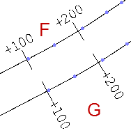
Spacing - Specify the distance between the major/primary tick marks to be drawn across/perpendicular to the alignment. |
|
|
Layer - Select a layer on which to place the major tick marks so you can show/hide them independently. |
||
|
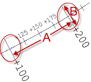
Tick size - Specify the length of the major tick marks (in sheet units). (See B in the image above.) |
||
|
Side - Select the location of the major tick marks relative (perpendicular) to the alignment.
|
||
|
Display whole station - Uncheck this box to display station values with formatting, e.g. whole station = 2; with formatting = 2+00. Note: The format depends on the station formatting set in Project Settings > Units > Station. |
||
| Text
|
||
|
Label every - Specify the interval at which the major tick marks should be labeled. |
||
|
Layer - Select a layer on which to place the text that is associated with the major tick marks. |
||
|
Text style - Select a style that controls the text font, font style, justification, and size for the alignment labels. |
||
|
Side - Select the location of the label text relative to the major tick mark/side of the alignment based on the point of beginning (POB).
|
||
|
Orientation - Select whether to orient the text labels tangent (roughly parallel to the alignment) or perpendicular to the alignment.
|
||
|
Set as default - Click this to save your label settings to Project Settings, which can then be saved in a project template. |
||
|
Apply - Click this to see your changes to the labels in the Plan View without leaving the Alignment Label Settings dialog. |
||
|
Minor |
||
|
Generate point on stations |
Check this box to generate points on intermediate stations. These use the same names as the labels. |
|
|
Label intermediate stations - Check this box to show/hide the minor ticks and their associated labels. |
||
| Ticks and text |
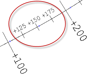
For the minor tick mark settings, see the descriptions for the major tick marks above. Minor tick marks are set at a defined interval between the major tick marks.
|
|
|
HAL Points |
||
|
|
||
|
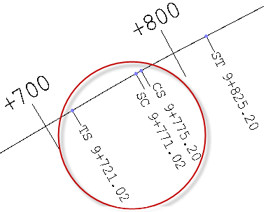
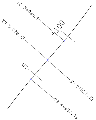
Label alignment points - Check this box to show/hide key points and their associated labels along the alignment. Abbreviations for these points are set in Project Settings. They can be found by selecting Project Settings > Abbreviations > Key Horizontal Alignment Points. |
||
| Line |
Layer - Select a layer on which to place the leader lines that connect the HAL points to their labels so you can show/hide them independently. |
|
|
Line length - Specify a length (in sheet units) for the leader lines. |
||
|
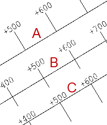
Side - Specify whether to display the HAL point labels on a side of the alignment or on inside or outside curves. The image below shows the labels displayed on inside curves.
|
||
| Text |
Layer - Select a layer on which to place the HAL point labels so you can show/hide them independently. |
|
|
Text style - Select a style that controls the text font, font style, justification, and size for the HAL point labels. |
||
|
Location - Specify whether to place the labels for the point Ahead or the point behind (Back). |
||
|
Label template - To append text to the HAL point abbreviations (defined in Project Settings), type the text you want to include before and/or after the * and ^ variable characters. * indicates where the abbreviation (e.g., PT, PC, PI) will appear. ^ indicates where the value for the HAL point will appear. You can move the characters to any positions in the label. If you remove the characters, the HAL point information will not appear in the Plan View. |
||
|
Station Equations |
||
| Line |
Layer - Select a layer on which to place the station equation tick marks. |
|
|
Line length - Specify a length (in sheet units) for the leader lines that connect the locations at which stationing changes and the associated station equation labels. |
||
|
Justification - Specify whether to display the HAL point labels on a side of the alignment or on inside or outside curves. |
||
| Text |
Layer - Select a layer on which to place the station equation labels. |
|
|
Text style - See the description for Text style above. |
||
|
Label ahead template - See the description for Label template above to see how the template applies to station ahead and station back labels. |
||
|
Label back template - See above. |
||
|
General |
||
|
Elevate ticks and labels - Check this box to raise the alignment labels described above to a certain height above the alignment's vertical alignment (VAL) so they can be seen when the VAL coincides with a surface that would obscure the labels. |
||
|
Elevation offset from VAL - Specify the distance above the VAL that you want to elevate its labels. Note: This is valuable when using the 3D Drive View if the labels might be obscured by the corridor surface you are trying to investigate. This setting enables you to raise the alignment labels above the surface. |
||