3D Drive View
Use the 3D Drive View to visualize and check for accurate topography of a surface by simulating a drive along a selected alignment or on the surface itself.
This topic includes the following sections:
- To drive along an alignment - This workflow allows you to drive along an alignment with both a horizontal and vertical component (HAL/VAL) to check for accurate topography of the surrounding surface.
- To drive across a surface - This workflow allows you to drive in any direction across a selected surface to check for accurate topography. Optionally, you can select to drive across one of two selected surfaces to identify cuts and fills. For example, you can drive across a final graded surface to identify cuts and fills related to the original ground surface. In addition, you can select to "self-drive" along an existing line or alignment in your project.
Prerequisites:
- See the Subscription Plans page. For a license matrix by command, see the License page in the TBC Community. Also see View and manage licensed features.
- Alignment with both a horizontal component (HAL) and vertical component (VAL)
(for the alignment-based 3D Drive View) - Surface, which can be of any type: generalized, corridor, planar, layer-based, depth-based
(for the surface-based 3D Drive View)
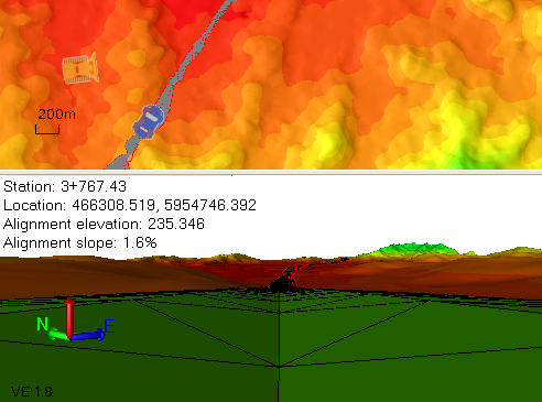
For an automated drive through, there is a setting to control the driving speed. An optional heads-up, textual display in each view shows the current station/location, surface/alignment elevation, and surface/alignment slope.
The 3D Drive View can be floated and moved to a second monitor by selecting Float View in Views > View or by clicking in the view and selecting Float View from the context menu. Where the 3D View is an orthographic view, the 3D Drive View is a perspective view.
View Filter Manager settings enable you to control the visibility of the surfaces and objects that are displayed, and you can edit objects to see the results while driving through the model. When driving, you can also 'look' in any direction; the direction of the vehicle is controlled independently. A car icon is used when driving along an alignment and a bulldozer icon is used when driving across a surface.
To 'drive' along an alignment in a 3D view:
- Select the alignment in the Project Explorer or a graphic view, and do one of the following:
- Right-click and select New 3D Drive View from the context menu.
- Select 3D Drive View in Corridors > Corridor.
A 3D Drive View opens with the viewpoint set at the point of beginning (POB) of the alignment.
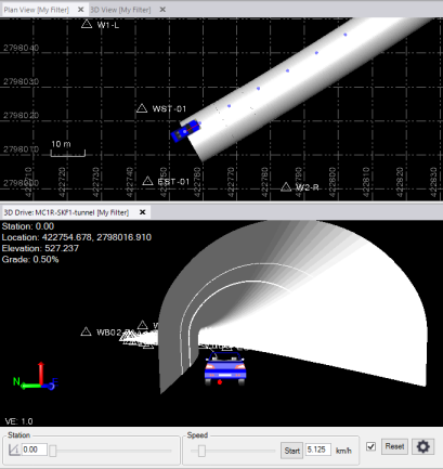
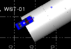
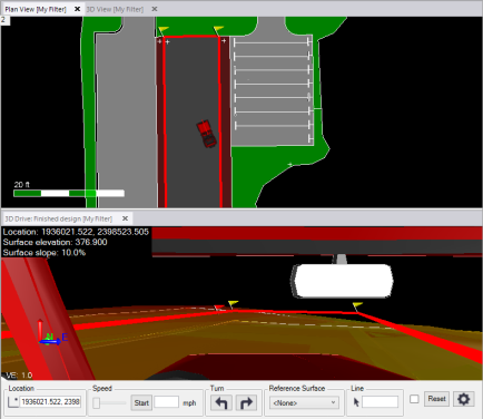
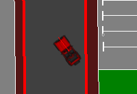
 In the Plan View, your 3D Drive View location and direction is represented by the blue vehicle icon. When you change your view from facing straight ahead, the direction of the viewpoint is indicated by the red line emanating from the center of the vehicle icon.
 - Click the Start button to move across the surface.
- Adjust the movement by:
- Clicking and dragging the slider next to the Station box.
- Clicking and dragging the Speed slider.
- Typing a speed (in kilometers or miles per hour, depending on your current unit settings) in the box next to the Start button and clicking Start. This speed may exceed the upper limit on the Speed slider.
- Pressing the [Up Arrow] and [Down Arrow] keys keys on your keyboard to change the speed by smaller increments (when focus is on the Speed slider).
- Pressing the [Page Up] and [Page Down] keys to change the speed by larger increments (when focus is on the Speed slider).
- To view a specific location along the alignment, type a station value in the Location box and press [Enter].
The drive stops when it reaches the end of the alignment. When driving along an alignment, the elevation reported is that of the alignment object at the current station. However, the elevation of the view point is affected by the viewpoint height, normally established above the vertical alignment, as described further below.
To 'drive' over a surface in a 3D view:
- Select the surface (or cut/fill map) in the Project Explorer or a graphic view, and do one of the following:
- Right-click and select New 3D Drive View from the context menu.
- Select 3D Drive View in Corridors > Corridor.
A 3D Drive View opens with the viewpoint set to an arbitrary location on the surface.
 In the Plan View, your 3D Drive View location and driving direction is represented by a yellow bulldozer icon: When you change your view from facing straight ahead, the direction of the viewpoint is indicated by the red line emanating from the center of the bulldozer icon.
 - Specify a starting location on the surface by:
- Clicking in the Location box and picking a new location in a graphic view.
- Typing a new coordinate in the Location box and pressing [Enter].
- Click the Start button to move across the surface.
- Adjust the movement by:
- Clicking and dragging the Speed slider.
- Typing a speed (in kilometers or miles per hour) in the box next to the Start button and clicking Start. This speed may exceed the upper limit on the Speed slider.
- Pressing the [Up Arrow] and [Down Arrow] keys on your keyboard to change the speed by smaller increments (when focus is on the Speed slider).
- Pressing the [Page Up] and [Page Down] keys to change the speed by larger increments (when focus is on the Speed slider).
- Change the direction of travel across the surface by:
- Clicking the
 and
and  arrow buttons to turn in 10° increments.
 - Pressing the [Back] and [Forward] keys (also labeled [Home] and [End]) to turn in 5° increments (when focus is on the turn arrows).
The drive stops when it reaches the edge of the surface. When driving over a surface, the elevation reported is that of the surface at the currently reported location. However the elevation of the view point is affected by the viewpoint height, normally established above that surface, as described further below.
- Clicking the
Values displayed in the view:
- For the 3D Drive View along an alignment, the station, location (coordinate), alignment elevation, and VPI alignment slope are shown.
- For the 3D Drive View across a surface, the location (coordinate), surface elevation, and surface slope (of the current triangle) are shown in the upper left of the graphic view.
Values are only shown when they are valid/applicable.
- To hide/show the values, click Project Settings > View > 3D Drive View and set Show alignment statistics and Show surface statistics to Yes or No.
- To adjust the viewpoint, click Project Settings > View > 3D Drive View and set Alignment viewpoint height, Use third-person view of vehicle, Third-person surface viewpoint height, and Third-person viewpoint distance behind vehicle.
- To change the vehicle type, click Project Settings > View > 3D Drive View and select the Vehicle type from the dropdown list.
- To change the font used for the display, select Options in the Quick Access Toolbar and select Startup and Display > Gridline and scalebar labels.
To change the perspective of the 3D Drive View:
The 3D Drive View is a modified 3D View, so any settings that affect the 3D View also affect the 3D Drive View. The default viewpoint is vertical (parallel to the horizon), not perpendicular to the vertical alignment or surface triangle the viewpoint is currently above. The viewpoint's eye height is set from the surface or the alignment, depending on the object selected for the view. You can rotate the viewpoint and exaggerate the vertical scale using the 3D View Settings or the gestures below.
Note: Panning actually only rotates the view and zooming only skews the perspective. The viewpoint does not actually change.
- To adjust the height of the viewpoint above or below the alignment, click Project Settings > View > 3D Drive View and change the Alignment or Surface viewpoint height in Project Settings.
Note: You can also access this setting by selecting 3D Drive View.
- To change the view, use any of the standard 3D view tools, such as:
- To zoom in and out, roll the mouse wheel.
- To increase the vertical exaggeration, press [Ctrl] + [Shift] and roll the mouse wheel.
- To move the viewpoint in any direction, press [Ctrl] and click and drag the mouse wheel or middle mouse button.
- To rotate the view angle vertically, press [Ctrl] and roll the mouse wheel.
- To rotate the view angle horizontally, press [Shift] and roll the mouse wheel.
Tip: This enables you to turn the viewpoint around to 'drive' the alignment in the opposite direction when in an alignment-based 3D Drive View, or to look to the side as you drive along in either an alignment-based or a surface-based view.
- To change the viewpoint from first-person to third-person, click the Display the camera using third-person perspective checkbox. If the Enable look around mode checkbox is selected, only the third-person viewpoint is available.
- To anchor the view rotation, click the Enable look around mode checkbox.
- To reset the view/realign the view with the vehicle icon's direction of travel, select Zoom Extents.
Scenario:
- If you select a corridor for the view, the values displayed are for the surface. To see values for the alignment on which the corridor is based, select that alignment for the view.
To drive along an alignment:
- In the Project Explorer or graphic view, right-click the alignment and select New 3D Drive View (or select 3D Drive View in Corridors > Corridor > Create Corridor).
A 3D Drive View tab opens with the point of view, represented by a vehicle icon on the Plan View, positioned at the point of beginning (POB) of the alignment.
Station, location, alignment elevation, and alignment grade statistics for the current position of the vehicle on the alignment are displayed in the upper-left corner of the view. (The station and location are indicated in the Plan View by the center of the vehicle icon.)
Optionally, using the View > 3D Drive pane in the Project Settings dialog, you can:
- Select whether to show alignment statistics in the graphic view.
- Select whether to show a third-person view of the vehicle.
- Select the vehicle (or person) icon to display.
- Specify the viewpoint in relation to the alignment and the vehicle.
For more information, see the "3D Drive View" section of the table in View Settings.
- To change Project Settings, click the Project Settings button
 located in the lower-right corner of the 3D Drive tab to display the related project settings in the Project Settings dialog.
Note: Optionally, you can use the View Filter Manager settings to control the visibility of the surfaces and objects that are displayed in all graphic views, including the 3D Drive View, and you can edit objects to see the results while driving along the alignment.
- To move along the alignment, do any of the following:
- Enter a specific station in the Station field and press the Tab key to move the vehicle directly to that station.
- Move the vehicle to any station using the Station slider control.
- Use the Speed slider control to specify the speed of the vehicle along the alignment, and then click the Start button. Click the Stop button to stop the vehicle at any time; press Start to restart it. The vehicle will stop automatically when it reaches the end of the alignment.
 Additional speed options...
Data displayed in the upper-left corner of the view is updated dynamically.
- To change your view direction (that is, look to the right or left, or behind you), press and hold your mouse wheel and drag you cursor on the view. Additional viewing options...
The red line on the vehicle icon in the Plan View indicates the current view direction.
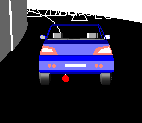
The red dot beneath the vehicle icon in the 3D Drive View indicates the precise location of the vehicle on the alignment.
- To zoom in or out of the view, hover your cursor over the view and roll your mouse wheel.
- To reset the default zoom level and default straight-ahead view, click the Reset button.
To drive across a surface:
- In the Project Explorer or graphic view, right-click the surface and select New 3D Drive View (or select 3D Drive View in Corridors > Corridor Create Corridor.)
If you plan to view cut/fill statistics comparing two surfaces (for example, "final grade" and "original ground"), select one of the two surfaces to be compared. You will select the second surface in step 3 below.
A 3D Drive View tab opens with the point of view (represented by a vehicle icon on the Plan View) positioned at the middle of the surface. Optionally, you can switch the view perspective between first-person (view from inside vehicle) and third-person (view from above and behind the vehicle) as explained in Select Project Settings for the 3D Drive View.
Location, surface elevation, and surface slope statistics for the current position of the vehicle on the surface are displayed in the upper-left corner of the view. (The location is indicated in the Plan View by the center of the vehicle icon.)
Optionally, using the View > 3D Drive pane in the Project Settings dialog, you can:
- Select whether to show surface statistics in the graphic view.
- Select whether to show a third-person view of the vehicle.
- Select the vehicle (or person) icon to display.
- Specify the viewpoint in relation to the vehicle.
For more information, see the "3D Drive View" section of the table in View Settings.
- To change Project Settings, click the Project Settings button located in the lower-right corner of the 3D Drive tab to display the related project settings in the Project Settings dialog.
Note: Optionally, you can use the View Filter Manager settings to control the visibility of the surfaces and objects that are displayed in all graphic views, including the 3D Drive View, and you can edit objects to see the results while driving across the surface.
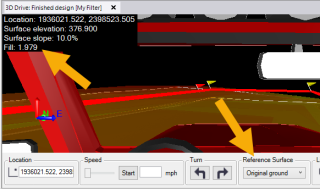
- Optionally, to view cuts and fills between the currently selected surface (for example, "final grade") and a different surface (for example, "original ground"), select a second surface in the Reference Surface drop-down list.
Cut and fill statistics are included along with other surface statistics displayed in the upper-left corner of the view.
- To move along the surface, do any of the following:
- Enter a specific coordinate in the Location field and press the Tab key to move the vehicle directly to that coordinate.
- Use the Speed slider control to specify the speed of the vehicle across surface, and then click the Start button. Click the Stop button to stop the vehicle at any time; press Start to restart it. The vehicle will stop automatically when it reaches the end of the surface. Additional speed options...
- Optionally, click in the Line field and select a line or alignment to be used to define the path of the drive. Then click the Start button to move along the selected line.
- Use the Turn buttons to turn the vehicle, whether it is stable or in motion. Each click turns the vehicle 10° in the direction selected. (Not applicable if a line has been selected in the Lock field.) Additional turn options...
Data displayed in the upper-left corner of the view is updated dynamically.
- To change your view direction (that is, look to the right or left, or behind you), press and hold your mouse wheel and drag you cursor on the view. Additional viewing options...
The red line on the vehicle icon in the Plan View indicates the current view direction.
- To zoom in or out of the view, hover your cursor over the view and roll your mouse wheel.
- To reset the default zoom and default straight-ahead view, click the Reset button.
