Profile View
Use the Profile View to check the geometry of a vertical alignment. The Profile View displays a vertical, graphic view of a single, specific alignment. When the alignment that the view is based on is modified or deleted, the view updates accordingly.
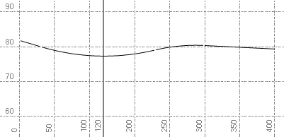
Figure: Profile View; The bold vertical line at 120 denotes a station equation.
Profile View coordinates
The profile view coordinate system is station and elevation. When entering coordinates, you can enter a relative distance (@100) and slope (-2%) as well as station and elevation. You may hold down ctrl +Shift and roll the mouse wheel to change the vertical exaggeration.
Note: The vertical exaggeration jumps to even intervals. Dealing with vertical exaggeration means that circular objects are not drawn circular. When the grid is displayed in this view the vertical exaggeration will also be shown.
Creating and editing objects in the Profile View
- As in the Plan View, you can create polylines, linestrings, and text in the Profile View. You can also edit objects using grips and snaps. When entering coordinates, you can enter a relative distance (@100) and slope (-2%).
Note: Ensure that grips are enabled before editing the created line.
- You can create a new vertical alignment (VAL) or append an existing VAL. The stationing of a new VAL will extend from the line being appended.
- The Profile View provides visual feedback when entering the slopes and distances for VALs; it displays the following on each VAL:
- vertical point of intersection (VPI) station and elevation
- Slope in to VPI
- Slope out from VPI
- Length of curve
- K factor of curve
- Station and elevation of VPC/VPT
- Station and elevation of high and low points
Note: The display of the VAL labels for each VAL can be turned ON/OFF in the properties pane.
- If you have imported profile objects into the plan view, where the x-coordinate is the station value and the y-coordinate is the elevation, you can copy this data from the plan view to the profile view. See Copy Objects to Profile View
- When you create a 'frame' in the view, a dynaview referencing the frame can be placed in sheet view to plot objects from the Profile View.
Note: By default, a vertical exaggeration is applied in the Profile View. To check or change the vertical scale, select Project Settings in the Quick Access Toolbarand select View > Profile View. You can also change the exaggeration in the view by pressing [Ctrl] + [Shift] and rolling the mouse wheel. The amount of exaggeration is rounded to preset values.
