Cross-Section View
Use the cross-section view to check surface cross-section geometry along a single, specific alignment anywhere it coincides with a single, specific surface. The cross-section view is a vertical, graphic view that changes depending on where you are along the alignment. The view also includes a slider and buttons for reviewing cross-sections at different stations. When the alignment or surface that the view is based on is modified or deleted, the view updates accordingly. Multiple cross-section views can be open concurrently.
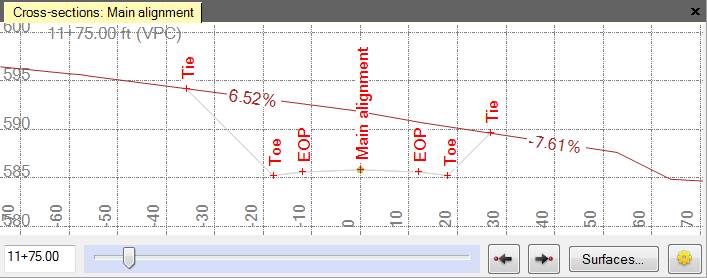
Red tic marks denote where the cross-section crosses points or breaklines. Bold vertical lines (not shown) denote station equations. At some view magnifications, the slope value is shown for each segment of the cross-section. You can also opt to show strata in the view.
Note: By default, a vertical exaggeration is applied in the Cross-section View. To check or change the vertical scale, select Project Settings in the Quick Access Toolbar and select View > Cross-section View. You can also change the exaggeration in the view by pressing [Ctrl] + [Shift] and rolling the mouse wheel.
