Create and View a Surface Cross-Section
Create a surface cross-section to check geometry along a single, specific alignment anywhere it coincides with a single, specific surface. To do this, the surface and alignment must be coincident. The view changes depending on where you are along the alignment. When the alignment or surface that the view is based on is modified or deleted, the view updates accordingly. Multiple cross-section views can be open concurrently.
Prerequisites:
- Alignment surface
To create a surface cross-section:
- Do one of the following:
- Select Create Surface Cross-Section in Corridors > Cross-Section.
- Right-click an alignment, and select New Cross-Section View from the context menu.
The Create Surface Cross-Section command pane displays.
- Select a surface in the Surface list.
- Select the coincident alignment in the Alignment list.
- Click .
To view a surface cross-section along an alignment:
- In the Project Explorer, select the alignment that coincides with the surface specified above.
- Right-click and select New Cross-Section View from the context menu. A cross-section view displays.
- To add additional surfaces to the view, click , and check boxes for the surfaces to include in the view in the Select Surfaces dialog. Click when you are done.
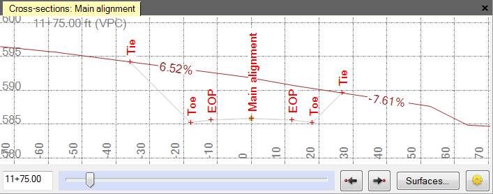
- Click and drag the slider at the bottom of the view to see the cross-sections along the alignment.
or
Type a station value in the box to the left of the slider to see the cross-section at a specific station. After you click in the station box, you can also move the cursor into the plan view and click anywhere along the alignment to specify the station.
Note: The cross-section view maintains the same scale as you move the station slider. Red tick marks denote where the cross-section crosses points or breaklines. Bold vertical lines denote station equations. At certain view magnifications, slope values appear above segments. To hide cross-section slope values, right-click the cross-section, and select Properties from the context menu. In the Properties pane, select Hide in the Label slope list.
Note: Two settings control how surface cross-sections are generated and displayed in this software. These settings are not available in Trimble Grade Control Systems (GCS). Therefore, when a road surface is exported to GCS, the cross-sections in the field software may be different than those in this office software.
