Create and Edit Text
Use the Create Text command to add single line or multi-line textual annotations and labels to your data. To create text along a line, see Scenarios below.
Labels and annotations help you identify the objects in your data. You can also edit imported text and text that you create.
Note: When you create text, it is created as a CAD multiline text object. When you import text, it comes in as either CAD text (single line) or CAD multiline text. You can make single line text into multiline text by double-clicking and editing it or clicking ![]() in the Edit Text command pane, not in the Properties pane.
in the Edit Text command pane, not in the Properties pane.
Prerequisites:
- None
To access the command:
- Select Create Text in Drafting > Text.
To create text:
- Use the options below and click Apply.
Options:
- Layer - Select the layer on which you want to display the text.
- Text style - Select a style that specifies the default text font, font style, justification, width factor, oblique angle, and height. If necessary, select <<New style>> to create a new style.
- Justification - Optionally, change the default justification, which specifies where the text is in relation to the insertion point, as well as whether multiple lines of text are left-, right-, or center-aligned.
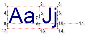
- Height - Optionally, change the default text height, which specifies the height of a capital letter from the baseline to the top line in ground units (see the diagram above). The text style allows you to specify the height of the text in either ground units or sheet units based on the current plot scale. When text is created, the size is always converted to ground units and saved as the height of the text.
|
Text Justifications |
||
|
1. Top left 2. Top center 3. Top right 4. Middle left 5. Middle center 6. Middle right 7. Middle mid |
|
8. Base left 9. Base center 10. Base right 11. Baseline 12. Bottom left 13. Bottom center 14. Bottom right |
|
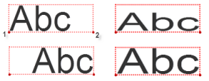
Text Alignments |
||
|
Base left justified
|
1. position 2. alignment point |
Base align justified
|
|
Base right justified |
Base fit justified |
|
- Rotation - Pick a rotation angle in the Plan View, or type an angle in the box. The rotation is clockwise around the text insertion point (as defined by the justification; see above) and zero rotation is due north.
- Width factor - Enter a factor (0 through 10, optionally including decimals) by which the text is stretched horizontally.
- Oblique angle - Enter an oblique angle (-85 through 85 degrees using whole numbers) by which the text is slanted.
- Leader type - Specify whether to include a leader line between the text and a point in a graphic view. You can choose a style with or without an arrowhead at the end of the line. Leader lines are used to connect annotations to particular points or objects when the text has been moved away from them to clarify the display. The orientation of a leader line will automatically update when you drag its associated text to a new position. Similarly, if the leader point is associated with an object, it will remain tried to that object if the object is moved.
Note: If you import and edit text that has a spline leader line, the spline displays as a straight leader line. Splines are not supported.
- Text - Type in the text field the text you want to display. Press the [Enter] key to create a new line. Optionally, press the Insert Smart Text button to insert smart text in the field.
- Leader point - If you specified to include a leader line, pick a point in a view or type a coordinate in the box to select the position at which you want the line to end (that is, at or near the object to which the text label applies).
- Text insertion point - Pick a point in a view or type a coordinate in the box for the origin of the text object. If you pick a 3D point, the elevation is also used. How the text is positioned in relation to the insertion point depends on the justification (see the diagram above). You can pick an insertion point in a 3D View as long as the target (for example, point, node, or vertex) can be snapped to.
- (other options based on a smart text target) - If you have inserted smart text, you may need to specify the target of the smart text and other objects on which it depends.
- (keyboard options) - These shortcuts are supported when you are editing an existing text after double-clicking it:
- [Control] + [C] to copy characters
- [Control] + [X] to cut characters
- [Control] + [V] to paste characters
These options, as well as Select All and Undo are available from a context menu when the text is in edit mode.
Note: Using [Control] + [Z] and [Control + [Y] will undo/redo changes at the command level, not for individual edits with a text object.
To edit text:
- Double-click a text object in the Plan View or 3D View. A blinking caret will appear within the text's bounding box. Then you can:
- Click within the text or press [<] and [>] arrow keys to move to a new position.
- Click-and-drag or press [shift] + [<] and [>] arrow keys to select characters to change.
- Insert characters at the caret's positon or over selected characters.
- Use [Control] + [C], [Control] + [X], [Control] + [V] to copy, cut, and paste characters within the string or from one text object to another. These options, as well as Select All and Undo are available from a context menu when the text is in edit mode.
- Press [Enter] to create another line after the caret.
While editing text using these options, you can zoom and pan the view or switch to other views without losing focus. To stop this dynamic editing mode, click outside the selected text's bounding box or press [Escape].
Note: When you double-click a smart text object, the code will display so you can edit the syntax.
- Select the text and do one of the following:
- Select the Edit Text command or right-click the text object in a graphic view and select Edit from the context menu. This displays the Edit Text command pane which allows you to perform any edits to the text object, including style, sizing, rotation, text, etc., based on the options below.
- Click the Text
 button in Properties pane for a selected text object to display the Text Editor dialog, which allows you to edit the text only.
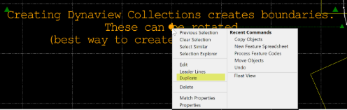
To duplicate and paste text
Use the Duplicate command in the pop-up context menu that displays in the Plan View, Sheet View, and Cutting Plane View to copy/paste existing text, and edit it as needed.
- Select the text in the graphic (plan view, sheet view, or cutting plane view) to be duplicated and right-click.
Select the text in the graphic view to be duplicated and right-click. - Select Duplicate in the context menu.
- Move your cursor to the spot you want to place the new text and click. The selected text appears in the Properties pane. //Move this second sentence to a new line (List Continue (TRMB). Try not to put action feedback on the same line as the step itself.
- Optionally, edit the new text.
Note: You cannot duplicate label text.
Entering text using an Input Method Editor
An input method editor (IME) is a Windows operating system feature that enables you to enter (in this case) foreign language characters and symbols that are not found on your keyboard. Using the IME that is enabled for the text editor lets you:
- Enter and edit Japanese or Chinese characters by typing and pressing [Spacebar].
- Choose from various typefaces based on the language you are using.
- Press [Escape] to undo your changes.
To invoke the IME
Your keyboard may have a special key to invoke the IME, but the Windows operating system allows you to configure a key combination for opening the IME, so virtually any key combination can be used. For more information, see the Microsoft article on Installing and Using Input Method Editors..
Scenarios:
- If your computer's font files do not contain the font specified for an imported CAD text object, the program's CAD text (failsafe) setting defines the font that is used. Specify the typeface to use for CAD text objects that reference a font that is either not included in the imported font's definition or unrecognized by your system by selecting Options > Startup and Display. Then specify the default CAD text (failsafe) under Fonts.
- In the Properties pane, you can set a Text Along property to Yes for a text object and then select a line (including arc segments) to align the text to it. When you move the line, the text moves with it. This works with multi-line text also.
- Select the text object in a graphic view.
- Press F11 to open the Properties pane.
- Under Appearance, set Text along to Yes.
- Click in the Line property field and pick the line you want to align the text with. Then you can also click-and-drag the circular anchor point to move text, which stays aligned with the line.
Notes:
- If you align text with arced line segments, it will curve also, but this curvature is not supported in Siteworks.
- A leader line is dependent on the text or object to which it is connected. If you move the text or object, the leader line adjusts accordingly; if you delete the text or object, the leader line disappears.
