Create and Edit a Surface Tie
Use the Create Surface Tie command to project a side slope connection (tie) up or down from a 3D line to a surface at specific cut and fill cross-slopes. Typically, a surface tie is used to project a ground surface embankment from a 3D site or roadway feature to an existing ground surface, or other surface as appropriate. A surface tie object can be added as a member of a surface, thereby representing the related side slope as a feature of that surface. A surface tie is dynamic. It updates with edits that you may make to the reference line from which it is projected, to the surface being intersected, or to the properties of that object. Surface ties can also be exploded so their projection and daylight lines can be used independently.
Note: You add more than one surface tie to a linestring. See To add multiple surface ties to a line below.

|
A surface tie is created from: 1. Surface to tie to 2. Reference line A surface tie consists of: 3. Projection lines 4. Daylight line where projection lines intersect the surface |
|
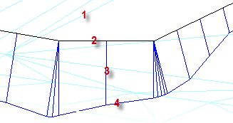
Figure: Parts of a surface tie
Prerequisites:
- Licensed module; See the Subscription Plans page. For a license matrix by command, see the License page in the TBC Community. Also see View and manage licensed features.
- Surface
- 3D line that is (at least partially) planimetrically coincident with the surface
Note: To be visible, the surface tie that is created also needs to be planimetrically coincident with the surface.
To access the command:
- Select Create Surface Tie in Surfaces > Create.
To tie a line to a surface:
- In the Name box, type an identifier for the surface tie object as you want it to appear in the Selection Explorer and graphic views. You can also use the name to select the tie in the Advanced Select command.
- Select the layer on which you want the surface tie to reside in the Layer list, or select <<New Layer>> to create a new layer for the tie.
- In the Tie to surface list, select the surface to which the reference line will be tied.
- In the Reference line box, pick (in a graphic view) the line that you want to tie to the surface.
- In the Direction list, specify the side of the reference line on which the projection lines to the surface should be created.
Note: The Left and Right options are based on the direction of the reference line. You can eliminate the need to be aware of that direction by just picking the appropriate side of the reference line in the Plan View.
- To show only the line created where the surface tie intersects with the surface (not the projection lines), check the Display daylight line only box.
- Specify the density of the projection lines by entering the maximum distance between each projection line (along the reference line) in the Maximum spacing box.
- In the Cut slope and Fill slope boxes, specify the cross-slope at which you want to project the tie from the reference line to the surface. To use a method besides the default, click the
 icon and choose an option:
 Slope percent - Enter the cross-slope from the reference line to the surface.
 Slope ratio - Enter the Rise to run or Run to rise ratio of the slope from the reference line to the surface.
Note: The ratio you specify depends on the Slope ratio type defined in Project Settings > Units > Vertical Angle. You can access this setting by clicking the Project Settings icon on the command's toolbar.
Note: Regardless of the Slope ratio type method you choose, the computed vertical angle is shown as a ratio in the Properties Pane.
Note: Depending on your cut/fill situation, you can leave either the Cut slope or Fill slope value blank; if you are certain that either value will not result in a tie, you need not specify it.
- In the Outside corner tie method list, select an option for how the tie's edge is formed at the surface:
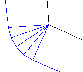
Round - Select this to produce a conical projection from an outside corner point, resulting in a generally rounded corner.
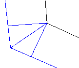
Sharp - Select this to produce a mitered solution where the side slopes are extended to their intersections.
- If you want the surface tie to be added as a member of a surface, select that surface in the Add to surface list.
- Click Apply.
- Repeat the steps above to create additional surface ties or click Close.
To edit an existing surface tie:
- Select the surface tie in a graphic view or the Selection Explorer.
- Right-click and select Properties from the context menu.
- Modify any of the editable values in the Properties pane, and press [Tab] to accept each change.
To add multiple surface ties to a line:
- Run the Create Surface Tie command and add one tie to a line.
- Run the command again and add a second tie to the same line at a different slope.
- Select one of the surface ties and press F11 to see its properties.
- Edit the Start tie and End tie properties.
Note: Because the last item can be set by clicking, and hence does not advance to the next control, the tie does not update until you tab to the next field.
- Repeat this process for each tie to limit each one to a separate distance along the line.
Note: Each tie is independent from the others; there is no prevention of gaps or overlaps, and no transition of the slope between two ties.
Limitations:
The portion of a surface tie object representing the daylight line is an approximation of the actual line that would be formed along the intersection of the projected side slope with the surface. The accuracy of that approximation can be increased by specifying a smaller maximum spacing value. In forming the surface tie object, each of the projection lines, as spaced using that value, is projected to its intersection with the surface. The daylight line then connects those intersection points at the end of the projection lines. Therefore, at each of those intersection points, the end of the projection line and the daylight line lies exactly on the surface. However, that portion of the daylight line between the projection lines is modeled as a straight line segment, which does not necessarily follow the true line of intersection and therefore may not lie precisely on the surface. The larger the maximum spacing value, the greater the daylight line representation is likely to deviate from the actual intersection of the side slope with the surface. As a practical matter, the approximation can easily be made close enough to meet any reasonable expectation.
Scenarios:
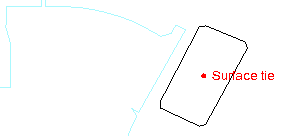
- If the surface tie cannot be computed for any reason, such as the reference line and the surface to tie to are not coincident, a selectable marker (labeled with the name of the surface tie) appears in the Plan View instead of the projection and daylight lines.
Dependencies:
- The surface tie object is dependent on both the reference line and the surface to which it is tied. If either of those objects change, the tie updates in response. If either of those objects is deleted, the surface tie will be deleted as well.
