Utility Pipe - User-Defined Utility Line Options
Use these options to create a custom utility line/pipe site improvement. The user-defined shape allows you to draw virtually any shape (that is then extruded) for use as a utility line. In this way, any shape can be applied to a line and created as a 'solid' with the specified shape.
Before or after you create a user-defined site improvement, use CAD commands to draw cross-sectional lines that describe the pipe's shape on on a layer that you can hide using the View Filter Manager. The shape should have multiple closed lines, such as one line for the inside of the pipe and one for the outside. You can then select the lines and apply a material between them to get the 'solid' part of the shape to have a color. If you have multiple closed areas, each one can have a different material. Curves are approximated for visualization. Finally, use the Edit User-Defined Utility Line Shape command to associate the shape with the site improvement. For more information, see Edit User-Defined Utility Line Shape.
|
Options |
||
| Name |
Type a descriptive name for the site improvement as you want it to appear in various commands that use pipes. |
|
| Utility type |
Select a Type for the network you will use this pipe in; it will not appear as an option for other types of networks.
|
|
| Shape |
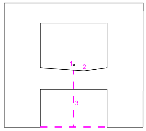
This shows the shape that is associated with the user-defined utility line site improvement. The Default shape is an open-topped, vertical-walled trough with the invert at 0,0 in the Plan View. Browse - After you create a user-defined utility line type here, click this button to close the dialog and open the Edit User-Defined Utility Shape command where you can specify the cross-sectional shape of the utility line. Once a shape is associated with a specific user-defined utility line, you can return to this dialog to change the association. Note: See the general workflow in Edit User-Defined Utility Line Shape before you click the Browse button because doing so will close the Material and Site Improvement Editor.
Figure: Height of user-defined shape |
|
| Class |
Enter the industry type or rating of the pipe (e.g., pressure or thickness). You can also use this text field to describe other properties, as needed. |
|
| Inside height |
Enter the distance from the invert to the highest open point of the pipe in small units. |
|
| Thickness |
For your own reference, enter the thickness of the pipe's wall in small units. Thickness is calculated from the actual user-defined shape. |
|
| Unit cost |
Enter the procurement unit cost of the pipe segment (per linear unit). Note: This program displays the currency symbol and format that you have set in Microsoft Windows® Regional and Language Options. The units and calculations, however, are not associated with a specific currency, so if a project is opened on a computer with different regional settings, those currency symbol and formats are used, but no conversion between currencies has been made. |
|
| Unit weight |
Enter the weight of the pipe or cable segment. |
|
| Unit length |
Enter the nominal length of the pipe or cable segment. |
|
| Primary inspection Additional inspection |
Inspection criteria is currently not implemented. |
|