Edit User-Defined Utility Line Shape
Use the Edit User-Defined Utility Line Shape command to define a custom shape for a utility line, which will then be applied to the associated user-defined utility line site mprovement and applied to pipes you create in your model. For more about predefined utility data that you can use, see Understanding Utility Networks.
General workflow for creating a user-defined utility line:
- Use CAD drawing tools (e.g. Create Rectangle, Create Circle, Create Polyline) in the Plan View to create the 2D geometry that you will need for the cross-sectional pipe shapes. Since these are just construction lines, you likely want to either:
- Create them away from your model, perhaps at 0,0,0 (when you select these lines in defining the utility line cross-sections, the inverts are at 0,0 by default).
- Create them on a layer that you will later hide using the View Filter Manager.
- Create all your user-defined utility line site improvements in the Material and Site Improvement Manager (MSIM). Also create materials from which the pipes will be built, as needed.
Note: It is important that you use a name that will describe the shape and size of the user-defined shape. Once the shape has been defined, it will only be selected by its name and you will not see the shape until it is applied to a line.
- Close the MSIM and open the Edit User-Defined Site Improvement command.
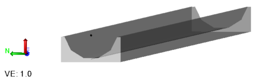
- Associate each user defined utility line site improvement with a cross-sectional shape by picking the appropriate CAD lines and specifying a material to use. You can also define more than one open area or more than one closed area for a material. In the pictures below, consider that the base could be one material, the sides and bottoms another and the lid another. You also define the invert for the shape. Otherwise it is assumed to be at 0,0. The centerline, top, left outside edge, right outside edge, and crown are calculated.
- Use the utility line site improvement like any other, as outlined in Create Utility Lines from CAD Lines and Create a Pipe (Utility Line) Between Nodes.
Sharing user-defined shapes across projects
It is recommended that you share utility objects via an external Material and Site Improvement Library (.mxl) because using a Project Link file (.vcl) will transfer all referenced/associated objects, such as surfaces, as well.
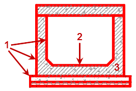
- Closed shape formed by CAD lines and/or linestrings
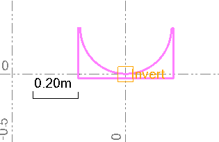
- Invert point
- Materials (shaded areas)
Figure: Parts of a user-defined utility line shape
Prerequisites:
- Licensed module; See the Subscription Plans page. For a license matrix by command, see the License page in the TBC Community. Also see View and manage licensed features.
To access the command:
- Select Edit User-Defined Utility Shape in Utility > Site Improvements.
To define a custom utility line shape:
- In the Utility Shape list, select the user-defined utility line site improvement for which you are defining the cross-sectional shape.
- From the Select lines box, pick CAD lines that represent the cross-section of the shape in the Plan View.
Tip: You may want to use the Track Region Outline command to extract complex cross-sectional geometry from a set of overlapping CAD lines.
Note: When you define a custom utility shape, the extrusion of the pipe comes out of the screen toward you. This means if you are looking at the start of the pipe in 3D, it will look reversed looking into the pipe, but will look correct looking at the last point of the pipe.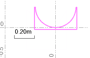
- In the Invert point box, pick the invert of the cross-sectional shape.
- Click in the Material locations box, and pick one or more points in the Plan View within the closed areas that you want the material to fill. The shape is filled with the material color in the enclosed area. When displayed, the pipe will get its color from this material.
Tip: Place the material 'seed' point near the invert of each user-defined shape so you can easily find it again, if needed.
Note: If the material is not placed correctly between closed lines, the pipe will not be visible in graphic views. To ensure the lines are closed shapes, you may need to select each, press [F11] to open the Properties pane, and set Closed to Yes.
Note: For built-in-place pipes, material volumes are calculated and can be reported in the Utility Takeoff Report.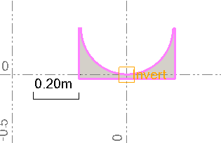
- Click Apply. Later, when you create user-defined utility lines that reference this shape, the shape is extruded along the length of the utility line.
Dependencies:
- All user-defined utility line site improvements that reference a shape are dependent; if you modify the shape, the site improvement definition and all modeled pipes of that type will all update accordingly. Modifying the CAD lines that the shapes are built from does not affect the shapes unless you recreate the shape from them.
