Create a Pipe (Utility Line) Between Nodes
Use the Create Pipe command to create utility lines, such as pipes or cables, from node to node in a utility network. Typically, creating nodes and pipes individually (where invert elevations are critical) is part of a more careful, manual approach for building gravity networks (as opposed to pressure networks in which pipes and nodes are created automatically). You will probably want to start with plans from a designer for gravity networks. Plans should include coordinates/locations of manholes and headwalls, diameters and types of pipes (in plan and profile), and elevations of pipes at junctions. As you create it, the network can be viewed in the Plan View and 3D View, as well as in the Project Explorer.
Pipe End Types
The ways in which designers and contractors measure and apply pipe lengths, elevations, and slopes varies across the world, so the program allows flexibility in modeling utility lines. Frequently, you will see the elevations of the pipe inverts and their lengths and slopes applied from center of structure to center. Obviously, for a gravity system you do not want to construct the pipe to the center of the node or no water can enter the pipe; therefore, the end of the pipe must be constructed some distance over. However, some people like to keep the elevation at the node center because that is where they locate their pipe laser, and that is where they want to hold the slopes.
If you hold the pipe elevation, and the length of the pipe is shortened to match what is actually used, then the slope will change. Trimble Business Center gives you the option of selecting where the pipe end will be located. The elevation will be at the end of the pipe and the slope is based on the end to end distances. You will need to consider this when you model your network.
Tip: You may want to open a 3D View next to your Plan View to see the pipes appear as you create them.
|
|
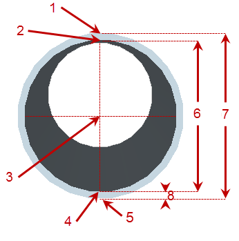
Figure: Parts of a pipe (cross-section)
|
|
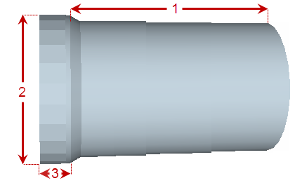
Figure: Parts of a pipe (profile)
Prerequisites:
- Licensed module; See the Subscription Plans page. For a license matrix by command, see the License page in the TBC Community. Also see View and manage licensed features.
- Utility network
- Utility run
- Two or more utility nodes (from and to)
- One or more pipe site improvements
To access the command:
- Select Create Pipe in Utility > Create Utilities.
- Right-click a utility node, and select Create Utility Line from the context menu.
To create a utility line:
- In the Utility network list, select the network of which the run is a part, or select <New> to create a new network.
- In the Utility run list, select the run in which the pipe should be included, or select <New> to create a new run.
Note: You can switch a utility line from one utility run to another in the Properties pane for the line, as long as the run you are changing to is in the same utility network. Each pipe must order the nodes appropriate for the node, meaning that each pipe should be from and to, downstream to upstream.
- Select an option for the end of the pipe in the Elevation type list (see images above):
- Bell - Select this to base the pipe end on the bell's elevation (see images above).
- Bottom - Select this to base the pipe end on the bottom elevation.
- Centerline - Select this to base the pipe end on the centerline's elevation.
- Crown - Select this to base the pipe end on the crown's elevation.
- Invert - Select this to base the pipe end on the invert's elevation.
- Obvert (soffit) - Select this to base the pipe end on the obvert's elevation.
- Select an option in the End type list:
- Calculated - Select this to place the pipe end's location at the point where it intersects with the interior wall of the node (1 in the image below).
- Center line - Select this to place the pipe end's location on the centerline of the intersecting node (2 in the image).
- Distance - Select this to place the pipe end's location on at a specified distance from the nodes centerline (3).
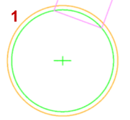
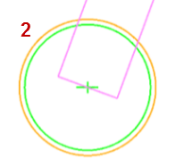
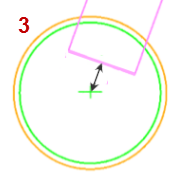
Figure: Pipe end types (plan view of pipe entering manhole)
- If you selected Distance as the End type, specify an Offset distance from the intersecting node's centerline.
- In the Name box, pick an object in a graphic view to use its name or type a unique identifier as you want it to appear in the Project Explorer and Selection Explorer. You can also use the name to select the pipe in the Advanced Select command.
Note: If you enter a number for the name, it will be auto-incremented for the name of the next pipe.
- Add notes about the type of pipe in the Description box.
- If the node you are adding is part of a utility network that has already been built on the site, check the Existing box so that it will not be counted in the Utility Takeoff Report.
- Select the layer on which you want the node to reside in the Layer list, or select <<New Layer>> to create a new layer for the node.
- Select an option in the Type list (see Utility Pipe - Circular Pipe Options for shape descriptions):
- Circular - Confirm this to use the default pipe which is cross-sectionally circular.
- Rectangular - Select this to use a cross-sectionally rectangular pipe shape.
- User-defined - Select this to use a custom pipe shape.
- Select the type of pipe or cable that you want to create between the nodes in the Site improvement list.
- If the site improvement type you need is not in the list, click the
 button to open the Material and Site Improvement Manager (MSIM).
 - Create the site improvement and click Close.
Note: If the Site improvement list is empty, confirm that your pipe site improvements reference the correct utility network type: pressurized, cable, or gravity in the MSIM.
- If the site improvement type you need is not in the list, click the
- In the From node list, select the node at which to start the pipe segment.
- In the Invert to inlet box, specify the distance from the invert of the node to the invert of the pipe, and enter the Inlet elevation.
Note: You can subsequently change the elevation of utility lines and nodes using the Change Elevation command. This includes the ability to change the in and out elevations of a selected line/pipe. To change just one end of a line, edit the elevation in the Properties pane for the selected pipe.
- In the To node list, select the node at which to end the pipe segment.
- In the Invert to inlet box, specify the distance from the invert of the node to the invert of the pipe, and enter the Inlet elevation.
Tip: This is useful when there is a constant drop through the manhole. The elevation of the node and drop are used to suggest the elevation of the pipe.
- Click Apply. The To node switches to the From node and the focus returns to the To node so that you can continue to create segments from the last node to the next node in a run. The pipe/cable segments appear under their parent run in the Project Explorer.
- Repeat the steps above to create additional utility lines/pipes.
- Click Close when you are done.
Dependencies:
- The created pipes/cables are dependent upon the utility network and run; if you delete the network or run, the pipes/cables are deleted too.
- The pipes/cables are dependent upon their site improvement definitions in the MSIM; if a definition changes, the instances of the site improvement used in your model are updated accordingly. There is one exception to this rule: Color is assigned to each utility line instance when it is first created, but it is not updated if the color of the site improvement's definition is changed in the manager.
