Change the Elevation of Objects
Use the Change Elevation command to elevate or change the elevation of one or more objects. You can elevate objects to a single absolute elevation, specify a relative change of elevation for objects, strip elevations from objects, elevate lines to a surface, or at an elevation defined by a vertical angle projected from a reference point.
Note: Most survey-related and raw data, such as points with control quality or local / global coordinates (in latitude and longitude), cannot be elevated. In addition, surfaces cannot be raised using this command; you must raise the members that are used to form the surface.
Prerequisites:
- Licensed module; See the Subscription Plans page. For a license matrix by command, see the License page in the TBC Community. Also see View and manage licensed features.
- Object to elevate
- 3D objects are required for the Delta elevation and Undefined elevation options
- 2D objects can be selected for the Absolute elevation, Surface elevation, and Relative to point options
To access the command:
Do one of the following:
- Select Change Elevation in CAD > Edit.
- Right-click a CAD point, and select Change Elevation from the context menu.
Dependencies:
- None; lines elevated to a surface are not dependent upon the surface once they are elevated relative to it. Points elevated relative to a reference point are not dependent upon the reference point once they are elevated.
To change the elevation of objects:
- Pick the objects you want to elevate in a graphic view, or click Options and choose a selection option from the menu.
- In the Apply group, select whether you want to apply:
- Delta elevation - Select this to move each of the existing elevations on each selected object by the vertical distance specified in the Delta elevation field. If a 3D polyline has segment end points at elevations of 5, 10, and 25, for example, and you move the polyline a relative elevation of 1, the end points are elevated to 6, 11, and 26. Generally, this should option should be used on 3D objects.
- Absolute elevation - Select this to set every elevation on each selected object to the elevation specified in the Elevation field. Generally, this option should use be used on objects that have only a single elevation or when the elevations of the nodes are the same.
- Undefined elevation - Select this to set the elevations of elevated points and linestrings to 'undefined' (denoted by a ? for the elevation property). Elevated polylines that you have created in your project are set to elevation 0.0.
Note: When imported CAD points and CAD lines have elevations of 0.0, it is assumed that their elevations are actually undefined, so this option does not affect them.
- Surface Elevation - Select this to elevate the selected objects to a surface (retains their planimetric locations). If needed, specify a Delta elevation above or below the surface that you select in the Surface list. Optionally, check the Drape only at vertices check box if you want to elevate only the vertices of the the selected objects to the selected surface elevation.
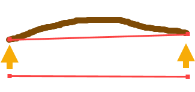
Otherwise, vertices will be elevated to the selected surface elevation and new vertices will be added at every point that crosses the surface's triangulation lines.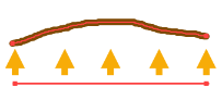
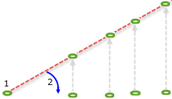
- Relative to point – Select this to change the elevation of point objects relative to a ray projected conically from any point at a specified vertical angle. Then select the reference point (1 below) and specify the vertical angle from that point (2). This is useful when you want to elevate objects to a hypothetical plane/design grade.
Note: If desired, click the
 icon to toggle the auto-advance mode on. When the icon looks like this
  , the value you entered will be held and this box will be skipped when elevating additional points.
Tip: You can toggle the Auto-advance mode on/off by pressing [Control] + [.] (period or decimal point).
- Click Apply. Repeat to elevate additional objects.
Tip: To elevate an object incrementally, select Relative change in elevation, specify the increment in the Elevation box, and click Apply repeatedly to apply the increment.
- Click when you are done.
