Understanding Utility Networks
The term 'utilities' covers a number of systems built on a construction site, including storm sewers, sanitary sewers, water lines, power lines, communication lines, cable networks, and similar transmission systems. In this software, utilities are grouped into three categories: gravity, pressure, and cable. Each of these utility types has specific properties related to how it operates, and limits the choices of site improvements that can be selected when building the network of pipes or lines for that type.
Gravity systems
In Trimble Business Center, gravity systems connect from node to node (e.g., manholes) using straight utility lines (e.g., pipes). If you have curved segments in such a system, they can be modeled by creating arc lines from node to node (and then using the Create Utility Line command to convert the arc into a pipe). Gravity systems are typically constructed from the lowest end to the highest so that if rain enters the trench it will drain down the constructed portion of the line.
Sanitary sewer lines typically start at 0.2 m/8” in diameter and are laid at 0.4 % slope, depending on the friction of the pipe material. Larger lines require less slope. Large storm drain lines may have a maximum slope so that the velocity of the water does not erode the pipe or ground downstream.
If you have multiple pipes coming into a single headwall, you can position the line that centers on the structure to use the headwall and then use a “null” headwall for the remaining pipes.
Pressure systems
Pressure systems are typically modeled with multiple line segments with nodes representing valves, bends, and junctions at intersections. You should first create one or more linestrings at the proper location and then use the Create Utility Line command to create a pipe at the same location. When using this command, the elevation of the linestring is used as the centerline of the utility line. This assumes concentric connections between different sizes and nodes. When converting the lines, the ends must match in 3D space (XYZ) so that a duplicate node is not created.
Cable systems
Cable networks are generally equivalent to pressure systems, but provide you with a different type of network so you can select from a limited list of materials based on this network type.
Methods for creating different types of utility networks
A utility network can be created by importing and converting a design file or by individually building and connecting utility runs, nodes, and lines/pipes.
There are two distinct approaches to creating utility networks:
- One is a more automated approach for creating pressure and cable networks. Typically, you will import a design file (such as LandXML, Trimble Business Center VCL, or CAD DXF/DWG) for pressure or cable networks. The imported lines can then be converted into runs, pipes, and nodes.
- The other is a more careful, manual approach for creating gravity networks where invert elevations are critical. In this method, you will likely start with plans from a designer/engineer. Plans should include coordinates/locations of manholes and headwalls, diameters and types of pipes (from plan and profile perspectives), and elevations of pipes at junction boxes, from which you can build a network piece by piece. For gravity networks that have curves or many segments, you can create linestrings and then elevate and convert them using the first method mentioned above.
Once created, a utility network can be viewed in the Plan View, 3D View, and Surface Slicer View, as well as in the Project Explorer. Applicable properties can then be directly edited in the Properties pane. By placing utility nodes and pipes on specific CAD layers, all (or portions) of a network can be more easily shown/hidden and selected.
Utility hierarchy
In TBC, utility systems can contain these objects:
- Network
- Run
- Nodes
- Pipes
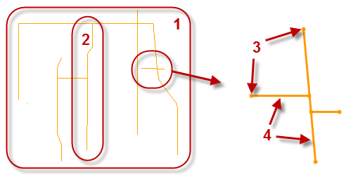
Figure: Parts of a utility network
Utility networks have these parent >child relationships:
- Networks include runs
- Runs include nodes and lines/pipes
- Nodes and pipes are defined by site improvement types
Site improvements
To model a utility network, you must first build a library of pipe and node types in the Material and Site Improvement Manager (MSI) using specific names, properties, and sizes for each object type. The MSI supports three generic categories of utilities: gravity, pressure, and cable. Within each category, you should group related/similar site improvements, like pipes, fittings, manholes, junction boxes, and headwalls. You can then select objects from this library when creating the pipes and nodes in runs that make up a network.
Networks
You can have as many utility networks as needed in a project. Each network can only contain utility lines and nodes of one type: gravity, pressure, or cable. This allows you to organize them by type, location, or any manner required. A utility network contains utility line/pipe/cable runs.
Runs
A utility run is defined by multiple lines/pipes/cables, and is also used to determine the direction of stationing along the run, as well as the order in which the pipes and nodes are reported in the Utility Takeoff Report. Each run has a beginning station so that all pipes and nodes can be reported by station. Pipe runs also help show the organization and correlation of utility objects in the Project Explorer. Utility nodes are part of a network, but are not a child of any specific run because they can be shared with multiple runs.
Nodes
Nodes are intended to schematically represent the ends of a utility line or junction of two utility lines. Most construction plans represent items such as valves with a symbol, rather than a complex model (block). This saves time in drawing the object and allows one symbol to represent multiple variations in shape and size.
A utility node is inserted when there is a change in a line/pipe/cable. Typically, nodes are used to define manholes, headwalls, tees, and junction boxes. In a gravity network, each pipe is typically a straight segment between nodes, so if there is a change in direction or slope in a run, a node is required. In pressure and cable systems, a ‘pipe’ can be a line with multiple segments that can change in direction. If there is a change in size, material, or a junction of multiple pipe runs, then a node must be inserted where the change occurs. Utility nodes are part of a network, but are not a child of any specific run because they can be shared with multiple runs.
There are four types of nodes; fitting, headwall, junction box, and manhole. Manholes and junction boxes are parametrically defined blocks; their real sizes can be closely approximated, but no attempt is made to model the various top-section configurations or entrances in detail. Headwalls are schematically represented with a user-definable block. Each manufacturer may have endless variations of a headwall. You can either apply the generic block supplied with the program and scale it as desired or you can create and import your own blocks with the desired level of detail.
Utility lines (pipes/cables)
The term 'utility line' is used generically to describe the linear transmission objects being installed, such as PVC pipe or communications cable. For gravity systems, the utility lines are typically straight pipes between nodes. In pressure and cable systems, the pipe can be lines with multiple segments (including arcs) that can change in direction.
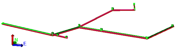
Colors, layers, and selecting utilities
Color can be helpful when used to code utility lines, so you should decide what color scheme you want to use before you create a lot of utility site improvements. One method is to color code networks by type. Here are recommended colors:
- Red = Electric
- Yellow = Natural gas, steam, oil
- Green = Sewer, drainage
- Blue = Water
- Purple = Reclaimed water
Consider making a range of colors for each type of network in order to convey size, but note that lighter colors may not work well on a white background. It is generally helpful to place each network type on a different layer (or series of layers) that also reflects the size or material being used. There are many ways to organize your data, so make a plan before you start. Consider creating different layers for nodes and lines within each run so that you can inspect each separately.
Graphic representations of site improvements
Utility objects can be represented both schematically (simple shapes) and (optionally) with more realistic blocks in the Plan View, Profile View, and 3D View. Pipes are positionally accurate, but most nodes are more schematic. For example, manholes and junction boxes are drawn by the program. They are open topped so that you can see how they terminate. For headwalls and fittings, you can assign blocks that will be drawn in the graphic views for each type of site improvement. A variety of blocks are available to schematically represent site improvements (see note below). You can also create (in Trimble SketchUp for example), import as CAD files (.dxf), and use your own 2D or 3D blocks at whatever detail and scale are needed. The furnished blocks are at a scale of 1" when the units are set to feet and 1.0 mm when set to meters.
Note: You can either import blocks (in CAD or Project link files (.vcl)) or use the Utility project template which includes many you might need.
In the case of a headwall, for example, you would create a site improvement for each size of headwall required. Each headwall can use the same block, but a 500 mm pipe would need a headwall with a scale factor of 500.
Making blocks for fittings, headwalls, etc.
When you create a fitting or headwall in the Material and Site Improvement Manager (MSIM) you get to specify which block to display in the graphic views. You should create such blocks at a scale of 1”/1 mm so that you can apply a multiplier depending on the size to be used. Use Sketchup to take advantage of the many shapes available in their library. Export from Sketchup as a DXF file, then clean the block up in Trimble Business Center and create the desired visual.
A generic block has been created to represent a fire hydrant and show how complex the representation can be. Note that the height from the centerline of the connection to the top of the fire hydrant is fixed. If different riser heights need to be modeled, you will either need to create specific blocks or name the site improvements appropriately. The following blocks are being furnished:
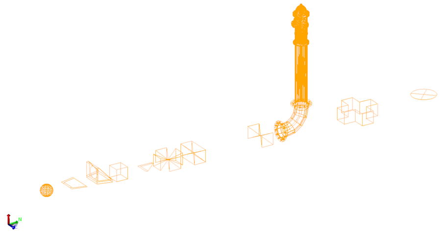
Figure: Fire hydrant and other blocks
Using predefined utility data
It is easiest to start your utility project with one of the installed utility project templates (.vct) that includes predefined utility objects. Alternately, you can create a new project and import a Project Link file (.vcl) that contains bounding lines for user-defined pipe shapes and a series of pipe objects that represent a variety of sizes. These utility-related objects are installed for you:
- project templates
- trench templates
- site improvements
- CAD blocks
Project and trench templates
There are two utilities project templates (imperial and metric) that include sets of trench templates, utility site improvements, and related blocks. You can start a project using one of these by selecting File > New, choosing one of the templates, and clicking OK.
Site improvements
You can open and use an external material and site improvement library (.mxl) with the predefined utility objects:
- Select Utility > Material and Site Improvement Manager > File > Open External Library.
- Browse to C:\Program Files\Trimble\Trimble Business Center\Support\iv\ and open Nodes and pipes in mm v 01.mxl or Nodes and pipes in inches v 01.mxl.
- Expand the Materials and Site Improvements groups in the explorer pane.
- Select a category or individual material or site improvement you need, right-click, and select Copy from Library to duplicate it in your project library.
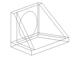
CAD Blocks
- In Windows Explorer, browse to C:\Program Files\Trimble\Trimble Business Center\Support\iv\.
- Locate the Project Link files (.vcl) files that include sample user-defined shapes (elliptical or virtually any other shape). These shapes will help you see how they are used in case you want to create your own shapes.
Workflow for using predefined utility data:
- Start projects using one of the utility templates (.vcts) by selecting File > New > select a Utility... template.
- Select Project > Import and bring in one of the Utility...shapes project link files (.vcl) that includes CAD blocks of manholes, headwalls, etc. from one of the paths listed below. These blocks are needed by the site improvement file you will import next.
- Select Utility > Material and Site Improvement Manager. Within the MSIM, select File > Open External Library and open a library (.mxl) from one of the paths listed below. The select the categories, site improvements, and materials you need and select Copy from Library to bring the objects you need into your project library.
- Now you are ready to work through some of the other steps outlined in:
Workflow: Create Gravity Utility/Trench Models
or
Workflow: Create Pressure Utility/Trench Models - Tip: You can rename predefined objects to names that match what you need, e.g., if you need a 13" pipe, but the library only contains a 12" pipe, that should be close enough.
Project templates (.vct)
(You can open these from within the program using File > New > )
- C:\Program Files\Trimble\Trimble Business Center\Support\en-US\Utility US Foot.vct
- C:\Program Files\Trimble\Trimble Business Center\Support\iv\Utility Meters.vct
- C:\Program Files\Trimble\Trimble Business Center\Support\en-US\Utility International Foot.vct
Project link files (.vcl)
You can import these from within the program using File > Import (or drag-and drop them in)
- C:\Program Files\Trimble\Trimble Business Center\Support\iv\Utility Pipe Elliptical shapes inches v 01.vcl
- C:\Program Files\Trimble\Trimble Business Center\Support\iv\Utility Pipe Arch shapes mm v 01.vcl
- C:\Program Files\Trimble\Trimble Business Center\Support\iv\Utility Pipe Arch shapes inches v 01.vcl
- C:\Program Files\Trimble\Trimble Business Center\Support\iv\Utility Node shapes mm v 01.vcl
- C:\Program Files\Trimble\Trimble Business Center\Support\iv\Utility Node shapes inches v 01.vcl
Material and site improvement libraries (.mxl)
You can open these files from within the Material and Site Improvement Manager
- C:\Program Files\Trimble\Trimble Business Center\Support\iv\Trial Material and Site Improvement Library (Meters).mxl
- C:\Program Files\Trimble\Trimble Business Center\Support\iv\Trial Material and Site Improvement Library (Feet).mxl
- C:\Program Files\Trimble\Trimble Business Center\Support\iv\Nodes and pipes in mm v 01.mxl
- C:\Program Files\Trimble\Trimble Business Center\Support\iv\Nodes and pipes in inches v 01.mxl
Labeling utility lines and nodes
Here are specific smart text codes for utilities, which you can cut and paste text to manually label utility lines and nodes:
Utility lines
- Name @<NM,O>@
- Desc. @<OD,O,de>@
- Site Improvement Name @<OD,O,SN>@
- Length @<OD,O,LL>@
- Slope Length @<OD,O,SL>@
- Slope: @<OD,O,S>@
Utility nodes
- Name @<NM,O>@
- Site Improvement Name @<OD,O,SN>@
- Desc. @<OD,O,DE>@
- Rim @<OD,O,RE>@
- Inv. @<OD,O,IE>@
- Station @<OD,O,RS>@
Combining corridor strata with site strata for utilities
To create strata surfaces that you can see in relation to your utilities, create and use corridor boreholes (which can be created without a corridor), not site boreholes. If you are doing a site takeoff in addition to a utility takeoff, you will want to combine the two types of strata.
- Create your site strata as you normally would. This will result in several strata layers being created.
- Create your corridor strata and use the Strata Definition Method of surfaces. Then select the surfaces being used by the site. Note that you can also select the Disable method to turn this off at a later time. Also note that once Corridor strata has been defined that this is the only way to turn off its use.
With strata properly defined, you can see earthwork cut volumes for utility trenches separated by strata.
Figure: Surface Slicer View of strata in relation to a utility line and trench
Importing pipes in LandXML files
If an imported pipe's properties are already defined in the MSIM, that definition is applied on import. If the imported pipe's name is the same, but the dimensions are different, a new MSIM object is created; the name is appended with the new dimensions. When imported, user-defined shapes from other programs come in as rectangular pipes defined by a cross-sectional bounding box.
