Find the Outline of a Region
Use the Track Region Outline command to create a 2D or 3D linestring representing the 2D outline of a region from a set of separate (potentially unconnected) lines and/or surface and site improvement edges. The region is derived from portions of the bounding lines/edges that planimetrically intersect (in Plan View) to form an enclosing region surrounding an interior 'seed' point. The region’s area is expanded outward from the interior point in all directions until a selected line/edge is encountered. The inverse is also true; you can pick an exterior seed point to get the outer boundary of selected lines.
Tracking a region outline enables you to create boundaries from lines/edges that may or may not intersect in 3D for commands, such as Define Area of Interest and Topsoil Stripping/Replacement, that require closed linework. Multiple outlines can be created sequentially, one at a time, without closing the command.
|
|
|
|
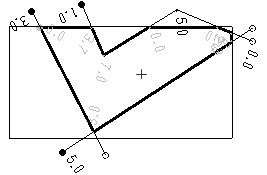
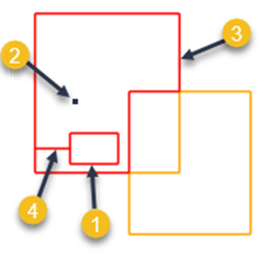
The image above shows the region outline created in the Plan View when all of the lines are selected and the interior point is placed at the + sign. The resulting linestring, which is closed in 2D, is formed from:
|
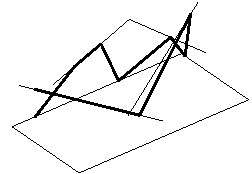
The image above shows the same region outline from an isometric angle in the 3D View. Generally, the 3D shape of the linestring is irrelevant to the commands in which it is used. For example, if used to define an area of interest, only the 2D region outline matters. The resulting linestring may or may not be closed in 3D. In this instance, it is not. Warning: Since the resulting linestrings are created for use as 2D outlines, their geometry is not appropriate for use as members of a surface. |
Prerequisites:
- See the Subscription Plans page. For a license matrix by command, see the License page in the TBC Community. Also see View and manage licensed features.
- Lines/edges that intersect planimetrically (in the Plan View) to form a closed region; these can include CAD lines, polylines, linestrings, breaklines, boundaries, and alignments and/or the edges of surfaces or site improvements that have been applied to surfaces.
To access the command:
- Select Track Region Outline in CAD > Edit.
Options:
- Name - A name is optional, but recommended to help you find the linestring that created when you want to select it in other commands.
- Lines - Select one or more lines (as defined in the Prerequisites) in the Plan View or 3D View, the Project Explorer, or Selection Explorer, or click Options and choose a selection method from the context menu.
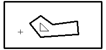
- Track interior regions - Check this box to create outlines from islands/holes defined by selected lines within the region formed by the outer selected lines. Only the first interior region encountered forms an outline linestring; islands/holes nested within interior regions are ignored. Below are examples of interior regions.
 or
or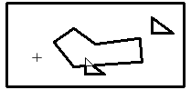
- Merge holes to boundary - Include the effect of inside linework in the tracked outline. Selecting three rectangles in this example and enabling this option:
- Inside linework (free-standing rectangle)
- Interior point selected
- Resulting tracked outline (in red)
- Line created by merging inside linework to tracked outline
- Gap closure tolerance - Specify the distance that line ends will be extended to close unintended gaps in the tracked outline. This tolerance is the maximum allowable gap between the end points of lines that will assume to be joined.
Note: The Gap Closure Tolerance is not intended to find large gaps, but rather small gaps that are typically found between end points of lines in CAD data, e.g., 0.1’ (depending on the scale of the data being analyzed). Setting this tolerance too high can cause undesirable results. The tolerance will not resolve the gap between a closed polygon and the endpoint of another line, only between the end points of lines.
- Interior/exterior point - Using this coordinate control, specify a point in the Plan View that is either bounded by the selected lines or lies outside of them.
Note: Each time you pick a point with lines selected, a linestring is created on the outline. If you pick multiple points with the same lines selected, identical linestrings are created.
- Results - The Region area is the total area bounded by the outer 2D outline. The Island area is the total area encompassed by all of the interior regions. The Net area is the total of the Region area minus the Island area.
Scenarios:
- If you need to make the resulting linestring 2D, select it and use the No Elevation option in the Change Elevation command.
Dependencies:
- The resulting linestring is independent of the lines from which it is created; if any of them are deleted or modified, the region outline does not change unless you recreate it.
