Create Fillets and Chamfers
Use the Fillet/Chamfer command to create a fillet line segment or chamfer line segment for two non-parallel line or arc segments.
A fillet line segment requires two specified line/arc segments and a specified radius.

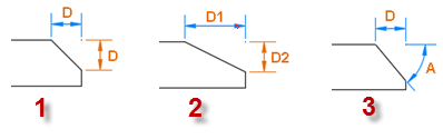
A chamfer line segment requires two specified line/arc segments and one distance (1 below), two distances (2 below), or a distance and an angle (3 below).
Prerequisites:
- Lines to fillet or chamfer
- See the Subscription Plans page. For a license matrix by command, see the License page in the TBC Community. Also see View and manage licensed features.
To create a fillet line segment:
- Select Fillet/Chamfer to display the Fillet/Chamfer command pane.
- Click in each of the Target line segments fields and pick the line/arc segments for which you want to create a fillet line segment.
Note: In some cases, the geometry of your lines will create different fillets depending on where you pick each segment. If your results are unexpected, try picking different locations along the line segments.
- In the Fillet radius field, type a radius distance to be used to create the fillet line segment. Or, click in the field and then "draw" the radius distance in the graphic view. If the specified radius is too large, you are presented with an option to use the largest valid radius.
To accommodate the radius you select, the selected line segments may extend automatically.
- Optionally, click the Auto-advance button
 located to the right of the Fillet radius field to "On" to enable you to create multiple fillets using the same radius without requiring you to click the Apply button each time.
 You only have to click the Apply button the first time, as described in step 6. Then you can continue to quickly create additional fillets by simply picking line segment pairs.
The fillet line segment displays in the graphic view.
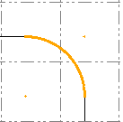
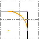
- To remove the parts of the selected line segments that extend beyond the new fillet line segment, check the Trim object box.
Trim entity checked:
Trim entity not checked:
- To calculate the fillet/chamfer using the entire line (rather than by specifying two sements) check the Apply to entire line box.
- When you are done, click the Apply button.
- Optionally, repeat this procedure to create additional fillets.
- When you are done, click Close.
To create a chamfer:
- Select Fillet/Chamfer to display the Fillet/Chamfer command pane.
- Click in each of the Target line segments fields and pick the line/arc segments for which you want to create a chamfer line segment.
Note: In some cases, the geometry of your lines will create different chamfers depending on where you pick each segment. If your results are unexpected, try picking different locations along the line segments.
- In the Chamfer mode drop-down list, select one of the three available modes as described in the beginning of this topic.
- One Distance
In the Distance field, type a single distance from the end of each of the selected line segments at which you want the new chamfer line segment to intersect. Or, click in the field and then "draw" the distance in the graphic view.
- Two Distances
In the first Distance field, type a distance from the end of the first selected line/arc segment at which you want the new chamfer line segment to intersect.
In the second Distance field, type a distance from the end of the second selected line/arc segment at which you want the new chamfer line segment to intersect.
Or, click in each field and then "draw" the distance in the graphic view.
- Distance and Angle
In the Distance field type a distance from the end of the first selected line/arc segment at which you want the new chamfer line segment to intersect. Or, click in the field and then "draw" the distance in the graphic view.
In the Angle field, type the angle from the first selected line for the new camfer line segment. Or, click in the field and then "draw" the angle in the graphic view.
- One Distance
- Optionally, click the Auto-advance button located to the right of any of the distance fields or the angle field to "On" to enable you to create multiple chamfers using the same distance and/or angle without requiring you to click the Apply button each time.
You only have to click the Apply button the first time, as described in step 7. Then you can continue to quickly create additional chamfers by simply picking line segment pairs.
- To remove the parts of the selected line segments that extend beyond the new chamfer line segment, check the Trim object check box.
- To calculate a fillet or chamfer based on the entire line rather than two segments you select, check the Apply to entire line box. For details, see Calculating fillets and chamfers in Entire line mode below.
- When you are done, click the Apply button.
- Optionally, repeat this procedure to create additional fillets.
- When you are done, click Close.
Calculating fillets and chamfers in Entire line mode
How the command determines the position of fillet arc and chamfer line:
Fillet:
The command computes offset lines of selected lines using the radius as the offset distance. The fillet arc is located at the intersection point of the offset lines.
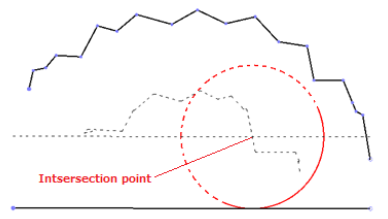
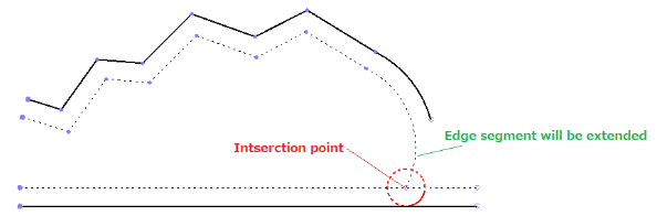
The command extends edge segments to compute intersection points ass shown below. If the edge segment is arc shaped, the segment is extended as an arc (for consistency with the segment-based mode).
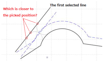
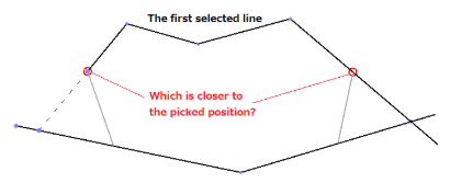
When there are multiple intersection points, the point picked on the selected line1 is used to determine which intersection point is used.
Chamfer:
The command computes an intersection point for the selected lines and then computes a position on the lines by the specified distance away from the intersection point.
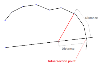
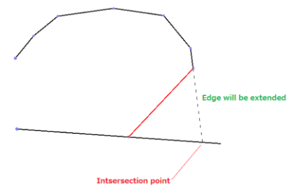
The command extends edge segments to compute intersection points as shown below.
When there are multiple intersection points, the point picked on the selected line1 is used to determine which intersection point is used.
Note:If you specify an invalid radius, a dialog will prompt you to confirm an automatic fix to make it a valid value. You can also opt to have the program fix the parameter without prompting you.
Scenarios:
- If a fillet's radius is too large, it is changed to the maximum allowed and a message alerts you to the change. If you accept, the new radius is used and the default radius persists as you entered it.
