Chamfer Using the CAD Command Line
Use the Chamfer command alias on the CAD Command Line to add a straight segment across the intersection of two non-parallel line segments by selecting the segments and specifing one or more distances and an angle. Chamfering bevels a corner.
Note: Like the pane-based Chamfer command, arc segments cannot be specified for the target line segments.
Prerequisites:
- Two non-parallel lines
- License; See the Subscription Plans page. For a license matrix by command, see the License page in the TBC Community. Also see View and manage licensed features.
To chamfer a corner:
- Press [F3] or click the
 icon on the Status Bar to open the CAD Command Line.
 - Type cha or CHA at the command prompt, and press [Enter].
- Skip the Layer, Color, and Line style lists below the command prompt; they do not apply to this operation.
- Pick the first line segment in a supported view (Plan View, 3D View, Sheet View, Cross-Section View, or Cutting Plane View), or type a keyword character to use another mode. The options are:
- Segment - Type S to fillet just selected segments. Then pick the second segment.
- Entire line - Type E to fillet an entire selected line. Then pick the line.
- If needed, enter T to toggle Trim off to retain the parts of the segments beyond the chamfer. Otherwise, those parts will be removed. The command remembers your selection the next time you run the operation.
Trim on
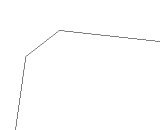 Trim off
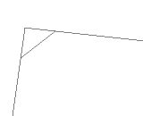
- Based on the One Distance mode highlighted at the prompt, enter a length for the chamfer segment, or enter a keyword character to use another mode. The options are:
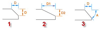
- One distance - Enter O and then the distance from the corner at which you want the new chamfer segment to begin (or pick two points in the view to specify the distance). The command remembers the last distance used the next time you run the operation. (See 1 below.)
- Two distances - Enter W and then the distance from the corner at which you want the chamfer to start on the first segment. Then enter the distance from the corner at which you want the chamfer to start on the second segment. Alternately, you can pick two points in the view to specify each distance. (See 2 below.)
- Distance with angle - Enter A and then the distance from the corner at which you want the chamfer to start on the first segment. Then enter the angle from the first segment at which you want the chamfer to start on the second segment. (See 3 below.)
A chamfer line segment requires two specified line segments and one distance (1 below), two distances (2 below), or a distance and an angle (3 below).
The chamfer is created. If lines do not cross planimetrically, the chamfer line connects the segment end points in 3D.
- Continue to pick pairs of segments to chamfer using the same modes (until you specify a new one). A preview of the chamfer that would be created based on the last selections is shown as you work.
- Press [Escape] to close the command or press [Spacebar] to rerun the command.
