Cutting Plane View
Use the Cutting Plane View command to create a profile view (cutting plane view) based on a specified 2D plane that allows you to "cut through" a point cloud, surface, 3D shell (for example, a pipe or cylinder), or SketchUp model for data viewing and capturing purposes. When using the Cutting Plane View command, you can specify the cutting plane's thickness to hide or show points as necessary to obtain the most optimal profile view. You can use the Cutting Plane View to create CAD line work right on the view (for example, linework tracing features on a building facade) that can be printed as a dynaview in a sheet set and/or exported to other applications via various CAD exporters.
Prerequisites:
See the Subscription Plans page. For a license matrix by command, see the License page in the TBC Community. Also see View and manage licensed features.
To use the Cutting Plane View:
- If it is not already displayed, display the 3D View.
- Select Cutting Plane View in Views > 3D View to display the Cutting Plane View tab, which typically opens directly beneath the 3D View tab.
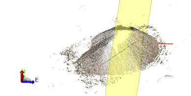
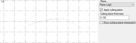
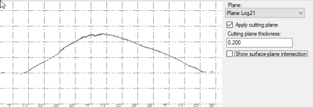
- In the Plane drop-down list, select the plane or plane set you want to use to define the orientation and position of the cutting plane view you will create, or select <New...> to create a new plane or subplane.
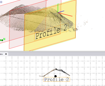
A yellow cutting plane displays in the 3D View at the same orientation and position as the selected plane.
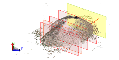
If you selected a plane set, each of the subplanes included in the set is displayed in the 3D View at its specified station along a linear path or axis path, depending on the plane type. The cutting plane can be moved to any of these predefined subplane positions (red outlines) very quickly as described later in this procedure.
Points intersecting the cutting plane (depending on the plane's specified thickness) display in the Cutting Plane View, providing a profile view based on the cutting plane's orientation and position.
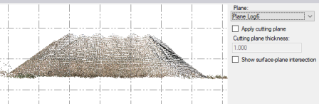
- To toggle between viewing just the points intersecting the selected cutting plane and all of the points displayed from the perspective of the cutting plane, check and uncheck the Apply cutting plane check box.
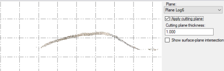
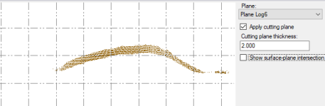
- Optionally, change the Cutting plane thickness value.
This determines the thickness of the cutting plane, which in turn determines which points are displayed in the Cutting Plane View. For example, a wider thickness will typically result in additional points being displayed in the view.
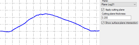
- If applicable, optionally check the Show surface-plane intersection check box to display a visual indicator of where the cutting plane intersects with a surface.
- Optionally, do any of the following to move the cutting plane to a new position along its linear path or axis path (depending on the plane type), updating the Cutting Plane View as it moves:
Note: A cutting plane based on a plane that was created using the From linear path option in the Plane Manager dialog will move along the path of its associated non-closed linear object, such as a linestring or an alignment. A cutting plane based on each of the other plane types will move along the path of the plane's axis, which is identified by the red axis line displayed with the cutting plane in the 3D View.
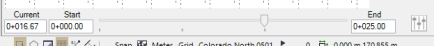
- Use the slider control located at the bottom of the tab to move the cutting plane to any position along its path.
- Select the edge of the cutting plane in the 3D View to activate its handle, which you can then use to drag the plane to any position along its path.
- Enter a new station in the Current field, which is located to the immediate left of the slider control, to move the cutting plane to that position along its path.
This allows you to either (1) offset the cutting plane from the original position for temporary visualization purposes or (2) create a new subplane at the new position.
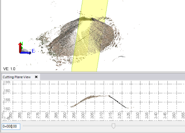
In the following example, the cutting plane is located at the origin position of the plane selected in the Plane drop-down list (that is, the position defined for the selected plane in the Plane Manager).
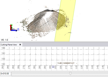
In this example, the cutting plane has been moved to station 0+010.00. Note the change to the profile in the Cutting Plane View.
- To add a new subplane based on the selected plane at the currently selected station, click the Add button (+)located to the right of the navigation arrows.
The new subplane is displayed in the 3D View and in the Project Explorer. If a single plane is selected in the Plane drop-down list, a new plane set is created that includes the selected plane and the new subplane. If you are basing the cutting plane on a plane set, the new subplane is added to the set.
- If you have selected a plane set in the Plane drop-down list, optionally do either of the following:
- Click the Slider options button located to the immediate right of the slider control and select Use subplanes. This causes a tick-mark to display along the bottom of the slider control at the station for each subplane in the selected plane set. As you move the slider to move the cutting plane, it will snap to a subplane station when you are near it. You can also use the two arrow buttons to move the cutting plane from one subplane station to another.
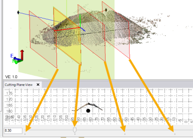
In the following example, the cutting plane has been positioned on the second subplane in the plane set and its profile view displayed in the Cutting Plane View. The black circle in the view indicates a linear object on which the selected plane, which was created using the From linear path option, is based.
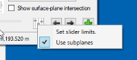
- To specify the start and end station for that part of the path you want to include in the Cutting Plane View when using the slider control, click the Slider options button located to the immediate right of the slider control and select Set slider limits.
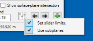
This causes an editable Start and End field to display on each side of the slider control. By default, these fields display the start and end stations specified for the selected plane set in the Plane Manager.
- Click the Slider options button located to the immediate right of the slider control and select Use subplanes. This causes a tick-mark to display along the bottom of the slider control at the station for each subplane in the selected plane set. As you move the slider to move the cutting plane, it will snap to a subplane station when you are near it. You can also use the two arrow buttons to move the cutting plane from one subplane station to another.
- Optionally, use the various CAD and drafting commands in TBC to create and edit CAD objects on the Cutting Plane View tab that display, as applicable, in the various graphic views.
Most CAD objects that are supported on the Plan View are also supported on the Cutting Plane View. This includes CAD polylines, linestrings, polygons, arcs and circles, rectangles, text, points (with World coordinates), and label tables. For example, you could trace the outline of a building facade and it's features and export it to another application. (See Work with CAD Tools for more instructions on creating CAD objects.) The Cutting Plane View also supports move/rotate/scale/copy commands and line editing commands (offset line, fillet/chamfer, trim/extend, clip, join, and break). The following example shows text that was entered on the Cutting Plane View.
You can also use the Measure Distance, Measure Point, and Measure Angle commands to make measurements on the plane.
You can create a dynaview on the Cutting Plane View tab, allowing you to display the CAD objects in a dynaview frame in the Plan View or insert the dynaview frame into a a sheet view that can be printed as part of a plan set. Or you can export a view to a DWG or DXF file. For more information, see Create a Dynaview.
