Create a Dynaview
Use the Create Dynaview command to add a frame around a portion of your model to have the frame's contents display at a location in paper space (in a Sheet View). Establish the size and shape of a dynaview by creating a frame (polyline, boundary, circle, rectangle, etc.) in the view around the objects you want to be shown through the dynaview. The frame cannot be placed in the 3D View.
Tip: Using Create Rectangle is the simplest way to make a frame for a dynaview.
Note: A dynaview's frame does not have to be a closed shape; it just has to be a shape for which the last segment can be added by the program to close it, i.e., a two segment polyline or an arc can be used.
Tip: You can apply a different view filter to each dynaview. In the View Filter Manager > Advanced View Filter Settings dialog, you can customize the appearance of lines per view filter; this allows you to set different colors, line styles, and line weights in different view filters for flexibility when plotting. For example, you may want a set of lines (such as contours) to be bold, colored, and solid in one dynaview but fine, black, and dashed in a different dynaview (even when they appear on the same sheet). These settings override the line color, weight, and style properties of the lines themselves.
You cannot select the objects within a dynaview to change them; only the original, model space objects can be changed. Dynaviews have these advantages:
- They save memory by plotting the original data and not making a copy.
- They are dynamic so that they update with changes in the original objects.
- When a dynaview is rotated, any text within it rotates automatically so that it reads correctly on the sheet.
- Each dynaview has its own view filter, so that the appearance of an area can be different in each dynaview on a page. You can change the view filter at any time by selecting the dynaview in the sheet view, right-clicking and selecting Properties, and then choosing a new view filter.
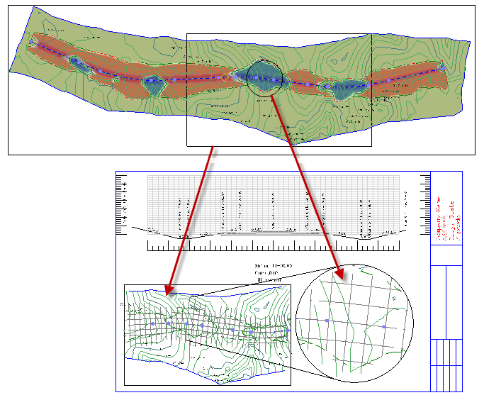
What Displays in a Dynaview
A dynaview displays exactly what is shown within its frame. Objects that cross the frame will be clipped in the dynaview, with one exception: text (see below). Dynaviews do not display the grid from the target view.
Text objects
Text is not clipped to the dynaview's frame. If any part of the text lies within the frame, Trimble Business Center draws the entire text object, even if it extends beyond the limits of the frame. This is done so that important labels and notes are not accidentially clipped. Text objects have two orientation properties:
- Auto-flip - Select Yes to have the text automatically flip (turn over) when it goes 12° past vertical in a rotated dynaview.
- Fixed orientation - Select Yes to keep the text at its original orientation even when it appears in a rotated dynaview.
Line styles
Line style patterns start at the clipped boundaries and hence the dynaview may not show a true picture of the original line pattern. In rectangular dynaviews, the line patterns will match the original. Line patterns and text in a dynaview are scaled according to the dynaview scale.
Note: Currently, surfaces, point clouds, other dynaviews, and objects from the 3D View cannot be shown in dynaviews.
Prerequisites:
- Licensed module; See the Subscription Plans page. For a license matrix by command, see the License page in the TBC Community. Also see View and manage licensed features.
- Model space objects in a Plan View or other view
- Plan set
- Sheet View
To access the command:
- Select Create Dynaview in Drafting > Dynaviews.
- Right-click on a line and select Create Dynaview.
To create a dynaview:
- In the Name box, type an identifier that indicates the contents of the dynaview.
- Select the layer on which you want the dynaview to reside in the Layer list, or select <<New Layer>> to create a new layer.
- From the Frame box, pick a closed shape (e.g., plotbox, rectangle, circle, polygon) in the Plan View to serve as the border of the dynaview.
- In the Scale box, specify the paper space scale at which you want the contents of the dynaview to appear in the Sheet View. The dimensions of your frame and its contents are divided by the value you enter as the plot scale. By default, the plot scale is defined in Project Settings > View > Plan View.
- Select a view filter to apply to the contents of the dynaview in the View Filter list.
- From the Location box, pick a point in a Sheet View at which you want to place the dynaview.
- If desired, enter an angle in the Rotation box or pick two points in the Plan View to specify a rotation angle. Positive rotation is clockwise and zero is due east.
Options:
- In any Sheet View, click the Refresh All button to update all sheet views and dynaviews with any changes that have been made to your model and at other paper space levels.
Dependencies:
- The contents of the dynaview are dependent on the objects within the dynaview's frame in model space. The dynaview will update when any changes are made to those objects in model space.
