Create and Edit Planes
Use the Plane Manager to define the orientation and position of a 2D plane that displays in your graphic views, allowing you to perform a variety of tasks. For example, you can use the plane to create a cutting plane which displays on the Cutting Plane View tab a profile view of all of the points in your project that intersect the cutting plane (based on the cutting plane thickness you specify), allowing you to perform checks on point clouds and surfaces, and create CAD linework directly on the plane. You can also use a plane to create an orthophoto from a point cloud, create a rectified image from station imagery, or create a projected surface.
When creating a plane, you have the option of replicating it along a linear or axis path at predefined intervals, creating a set of related suplanes called a plane set. This allows you, for example, to easily and quickly define a separate plane for each floor in a building, or provide profile views at predefined station intervals along a road corridor.
Prerequisites:
See the Subscription Plans page. For a license matrix by command, see the License page in the TBC Community. Also see View and manage licensed features.
To create a plane:
- Do either of the following to display the Plane Manager dialog.
- Select Plane Manager in Views > 3D View.
- In the Plane drop-down list on the Cutting Plane View tab or in a command pane that requires a plane (for example, Create Orthophotoand Create Rectified Image), select <New...>.
- In the Plane Manager dialog, click the New button and enter a name for the new plane.
- In the Plane list, select the orientation option you want to use to create the plane.
In the following example, the red line extending outward from the face of the plane indicates its axis.
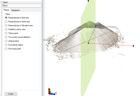
- Perpendicular to East/North/Elevation axis - Create a plane that is perpendicular to the East (X), North (Y), or Elevation (Z) axis. Then, click in the Position field and select a point in a graphic view, enter a point ID, or enter a 3D coordinate specifying the plane's position origin.
- Parallel to active view - Create a plane that is parallel to the active graphic view. Then, click in the Position field and select a point in a graphic view, enter a point ID, or enter a 3D coordinate specifying the plane's position origin. If you change the active view and you want that change to be applied to the new plane, click the Update button.
- Three points - Create a plane using three specified points from which a vector can be computed. Click in each of the Point fields and select a point in a graphic view, enter a point ID, or enter a 3D coordinate specifying the point's position. Then, click in the Position field and select a point in a graphic view, enter a point ID, or enter a 3D coordinate specifying the plane's position origin.
- Two points normal definition - Create a plane that is perpendicular to a vector computed between two points. Click in each of the Point fields and select a point in a graphic view, enter a point ID, or enter a 3D coordinate specifying the point's position. Then, click in the Position field and select a point in a graphic view, enter a point ID, or enter a 3D coordinate specifying the plane's position origin.
- Vertical plane - Create a vertical plane with a horizontal orientation using a vector computed between two points. Click in each of the Point fields and select a point in a graphic view, enter a point ID, or enter a 3D coordinate specifying the point's position. Then, click in the Position field and select a point in a graphic view, enter a point ID, or enter a 3D coordinate specifying the plane's position origin.
- From planar object - Create a plane based on the orientation of a CAD object or georeferenced image. Click in the Select object field and then select the object on which to base the plane. Then, click in the Position field and select a point in a graphic view, enter a point ID, or enter a 3D coordinate specifying the plane's position origin.
Note: If it is necessary to recreate the plane on which an orthoimage displays to view it in the Cutting Plane View (for example, the original plane was deleted or modified, or the orthoimage was imported into your project), you can use the From planar object option to select the orthoimage to recreate its original plane. If you want to select the orthoimage in a graphic view, you must ensure it is selectable in the Advanced View Filter Settings dialog.
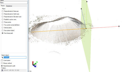
- From linear path - Create a plane that is based on a non-closed linear object, such as a linestring or an alignment. Click in the Select object field and then select the object on which to base the plane. The new plane is created at the beginning of the line, based on the direction in which the line was "drawn." To have it created on the opposite end of the line, check the Invert plane check box. Also, select whether the new plane is Vertical or Perpendicular to path. (The Position field specifying the plane's position origin is read-only.)
In the following example, you can see that the new plane is positioned at the beginning of the selected (orange) linestring (station 0+000.00) and is perpendicular to the linestring. Typically, this plane type is used to created subplanes at various positions along a linear path as described later in this procedure.
- If you selected a plane option other than From linear path, optionally click the Invert button to invert the plane.
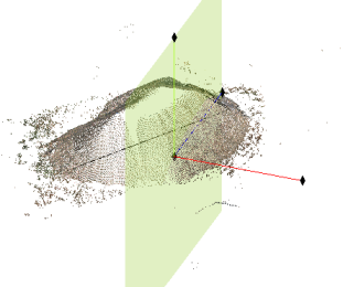
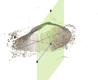
By inverting the plane, you change the face of the plane (the face on which you can draw CAD objects in the Cutting Plane View) from one side to the other. In the following images, note the location of the red axis line.
Before inverting:
After inverting:
- Do one of the following:
- If you are done creating planes, click the Close button to close the dialog.
- If you want to create additional single planes, click the New button and repeat these instructions.
- If you want to create a plane set from a plane—that is, replicate the plane along a linear path (From linear path option) or axis path (other Plane options) at predefined intervals, resulting in a collection of related subplanes—continue with the next step.
The newly created plane is available for selection in any Plane drop-down list. If you opened the Plane Manager by selecting <New...> in a Plane drop-down list, the newly created plane is selected in the list.
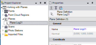
The newly created plane is also represented by a node nested beneath the parent Planes node in the Project Explorer. You can double-click the node to view the plane's properties and, optionally, change its name. You can also right-click the node and select Delete to delete the plane from the project.
- To create a plane set from a plane, do the following:
Notes:
- As an alternative to creating a plane set as described in this procedure, you can create a single plane and then use it to create subplanes and a plane set graphically using the Cutting Plane View.
- Plane sets are typically created based on a linear path (From linear path option), but they can be created based on the axis path of other types of planes as well, depending on the desired outcome.- With the desired plane selected in the list on the left side of the Plane Manager dialog, select the Subplanes tab.
- In the Path limits group box, optionally do either or both of the following:
- Enter or change the Start station and End station that define that section of the linear object path (From linear path option selected) or axis path of the plane (option other than From linear path selected) on which you want to replicate the selected plane.
- Select any of the Add check boxes to create subplanes at the specified locations.
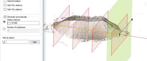
- Optionally, check the Generate automatically check box and do either of the following:
- Select the Station interval option and enter the station interval at which to create new subplanes.
This will cause a new subplane to be created at station 0+000.00 and each subsequent station at the specified interval.
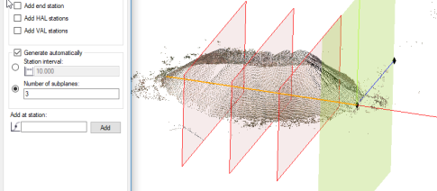
- Select the Number of subplanes option and enter the number of subplanes to create.
This will cause the specified number of subplanes to be create and evenly spaced between the start station and end station.
- Select the Station interval option and enter the station interval at which to create new subplanes.
- Optionally, to create an additional subplane at a specified station, click in the Add a station field and enter, or select in the 3D View, the station at which you want to add it and click the Add button. Repeat as necessary to create additional planes.

Changes you make to the plane set are saved in the project as soon as you make them.
The newly created plane set is represented by individual subplane nodes nested beneath the parent Plane node. You can double-click any of the nodes to view the plane's properties and, optionally, change its name. You can also right-click the node and select Delete to delete the plane from the project.
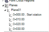
Note that three of the subplane node icons displayed in the example above include several vertical dots on their right side. This indicates that the subplanes were created automatically based on criteria selected in the Path limits and Generate automatically group boxes.

Note that one of the subplane node icons displayed in the example includes a plus sign instead of the vertical dots. This indicates that the subplane was created manually using the Add a station field.

To edit an existing plane:
- Do either of the following to display the Plane Manager dialog.
- Select Plane Manager in Views > 3D View.
- In any Plane drop-down list, select <New...>.
- Select the plane you want to edit.
- Make changes as necessary as described in the previous procedure.
- When you are done, click the Close button.
You might find it useful to leave the dialog open while working with related commands.
