Create Rectified Images from Station-Based Photos
Use the Create Rectified Image command to create a 2D orthoimage from photo images captured with a total station or other Trimble VISION enabled instrument. The command allows you to select or define an appropriate plane to use for the image, draw a rectangle to specify the real-world area on the plane to be covered, and select the pixel size for the resulting image.
After you create or import an orthoimage, you can optionally display it on the Cutting Plane View, where you can can make measurements and add text and linework to create deliverables. You can export the orthoimage using the Orthoimage exporter, or a DWG or DXF exporter, to share with other users. A text file that defines the coordinates (in meters) corresponding to the four corners of the image is also created to locate the image if it is imported back into a TBC project.
Prerequisites:
See the Subscription Plans page. For a license matrix by command, see the License page in the TBC Community. Also see View and manage licensed features.
To create a rectified image:
- Select Create Rectified Image in Point Clouds > Deliverables to display the Create Rectified Image command pane.
- In the Station drop-down list, select the photo station whose images you want to use to create the orthoimage.
The New Station View tab displays for the selected station.
- In the Name field, enter the name for the resulting orthoimage file and coordinates text file.
If you continue to use the same name for subsequent orthoimage files, the name for each new file will be appended with a sequential number.
- In the Plane Definition drop-down list, select the plane definition you want to use to create the orthomage, or select <New...> to create a new plane definition.
This is the plane on which you will draw a rectangle representing the borders of the orthoimage you will be creating (for example, a plane on the face of a building).
The selected plane is displayed in each of the graphic views.
Plan View:
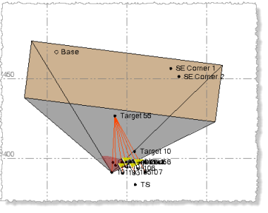
3D View:
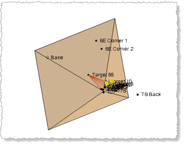
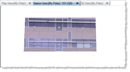
Station View:
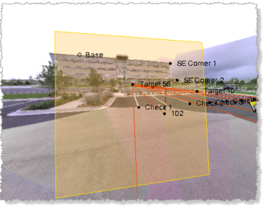
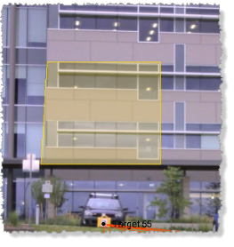
- In the Image rectangle fields, select a location or point (or enter a point ID) on the plane for each of the two opposing corners of the rectangle, which defines the borders for the resulting orthoimage.
The rectangle is automatically oriented to the plane.
- In the Pixel size field, enter the pixel size (resolution) to be used for the orthoimage.
For example, if you enter .001, each pixel will represent a 1mm x 1mm real-world area on the plane. The smaller the pixel size, the higher the resolution and the larger the resulting image file.
The Image info field updates dynamically as you draw the rectangle and enter a pixel size:
- Rectangle size - This is the real-world size of the area selected on the plane with the Image rectangle controls.
- Image size - This is the real-world size of the area on the plane to be included in the orthoimage. It may vary from the Rectangle size due to rounding required based on the specified Pixel size. The larger the Pixel size, the greater the rounding will be.
- Image resolution - This is the horizontal and vertical pixel resolution for the resulting orthoimage. It is determined by the Rectangle size and Pixel size. The larger the Pixel size, the lower the resolution. The larger the Rectangle size, the higher the resolution.
- Total pixels - This is the total number of pixels in the resulting orthoimage. determined by multiplying the horizontal and vertical Image resolution values.
Note: The Create Rectified Image command automatically renders multiple image "tiles" when creating a rectified image from a selection that exceeds GPU limitations of 16,384 pixels in each direction. The multiple image tiles are then combined into a single rectified image for import into your project. This allows you to make very large selections when creating rectified images, resulting in very larger images (up to 500 MP).
- Click the Create button.
Two new files are created in the project folder, each using the name specified in the Name field:
- An orthoimage file
- A text file that defines the coordinates (in meters) corresponding to the four corners of the image.
The orthoimage file is automatically imported into TBC and displays in the graphic views. You can use the View Filter Manager to display or hide orthoimages, or hide objects other than orthoimages (see below). In addition, you can right-click an orthoimage node in the Project Explorer (nested beneath the Import node) to view its read-only properties and change background transparency and rendering settings.
At this point, you can, optionally, display the orthoimage in the Cutting Plane View to use it to make measurements and/or create overlying linework.
Note: If it is necessary to recreate the plane on which the orthoimage displays to view it in the Cutting Plane View (for example, the original plane was deleted or modified, or the orthoimage has been imported into your project), you can use the From planar object option in the Plane Definition Manager to select the orthoimage and recreate its original plane. If you want to select the orthoimage in a graphic view, you must ensure it is selectable in the Advanced View Filter Settings dialog.
You can use the the Orthoimage exporter to export the orthoimage to share with other users. Or, you can use the DWG or DXF exporter to export the orthoimage and any selected linework to AutoCAD. See Export Data for more information.
