Create a Surface Intersection (point where a ray intersects a surface)
Use the Create Surface Intersection command to create a point on a surface at a given bearing and vertical angle from a specific position (reference point). Specify multiple bearings and vertical angles to create a series of surface intersection points connected by a linestring. This is useful when you need to calculate a daylight line, such as from the top of a pad down to an existing ground surface.
Prerequisites:
- Licensed module; See the Subscription Plans page. For a license matrix by command, see the License page in the TBC Community. Also see View and manage licensed features.
- Surface
To access the command:
- Select Create Surface Intersection in Surfaces > Create.
To create a ‘surface intersection’ point:
- In the Name box, pick an object in a graphic view to use its name for the linestring that connects the intersecting points, or type a unique identifier as you want it to appear in the Project Explorer and Selection Explorer. You can also use the name to select the linestring in the Advanced Select command.
- Select the layer on which you want the new linestring to reside in the Layer list, or select <<New Layer>> to create a new layer for it.
- In the Surface list, select the surface on which to create the intersecting points.
- In the Coordinate box, specify the reference point/viewpoint location by picking a point in a graphic view or typing in an X,Y coordinate.
- If you typed in a coordinate, enter the Z value/elevation in the Elevation box.
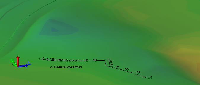
- Specify the direction of the ray going from the reference point to the surface by typing a value in the Bearing box or by picking the end of the bearing line. Positive rotation is clockwise and zero is due north.
- In the Vertical angle box, specify the angle at which to calculate the ray from the reference point to the surface. Typically, this will be specified as a ratio, such as -2:1.
- To create more than one intersection point, check the Multiple checkbox and follow the steps below.
- In the Number of points box, enter the total number of equidistant points to create between the first bearing and the final bearing.
- In the Point ID box, enter the starting point name and/or prefix and suffix. Point numbers auto-increment from the specified point ID. For example, if you enter “Pt 11 x”, subsequent points will be named “Pt 12 x”, “Pt 13 x”, etc.
- In the Final bearing box, specify the direction of the last ray going from the reference point to the surface.
- In the Final vertical angle box, specify the angle at which to calculate the last ray from the reference point to the surface.
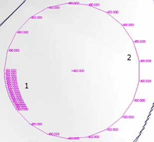
- By default, intersection points are calculated counter-clockwise from the first bearing to the last. To reverse this order, check the Clockwise box.
The default counter-clockwise and checkbox option enable you to create points for either the small (1 below) or large (2) arc from a 360º range.
- Select an option in the Linestring defined by group:
- Coordinate - Select this to create the linestring using the calculated coordinates at each node without creating point objects.
- Point ID - Select this to base the line segment end points on named point objects, meaning that if you move one of the points, the linesting's geometry will update.
- Click Apply to create a point object where the ray intersects the surface.
Dependencies:
