Apply a Tilt Rule
Tilt is an ‘other’ rule used to compute a vertical design that is interpolated from a surface described by the elevation, direction, and slope of the Tilt rule. To apply it, enter an elevation and slope and then pick a source and target line. The Tilt rule does not interact with any of the other rules. The Tilt rule is designed to handle different tilt issues around shaping intersections like roundabouts, etc. In such cases, it is necessary to handle the design’s entire geometry after certain requirements – where tilting geometry is one; all else is ignored for the line.
Conflict with other rules
The Tilt rule does not conflict with any other rules.
Tilt scenarios
Case 1
If you apply a Tilt rule with a negative slope value, the slope will compute a lower elevation the further away a point is. Depending on the shape of the target line, the elevation will vary accordingly.
Note: The length of the Tilt rule has an effect on the elevation at the Hit point on the target line, since the elevation is referring to the start point (enter a start coordinate and point for the target line to set the direction). The Tilt rule must have a length > 0.0 or it cannot find the direction of tilt.
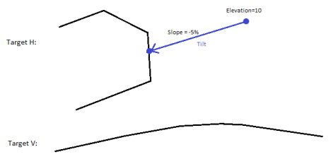
Figure: (represented in plan perspective above and profile below)
Case 2
If you apply a Tilt rule with a positive slope value the vertical result is inverted as compared to Case 1 above. The orientation of the tilt is handled by the Slope and Direction. Elevation has the role of setting a vertical offset.
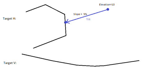
Figure: (represented in plan perspective above and profile below)
The Tilt rule has no property that shows the elevation at the target line’s hit point, nor any pivot point to anchor any elevation of the vertical alignment (VAL).
To apply a Tilt rule:
- Enter an Elevation.
- Enter a Slope.
- Pick a point along the line (or enter a Start coordinate).
- Pick a Target line.
- Write a Description of the rule.
- To place this rule above the previous, check the Insert above selected rule box.
- Click the Add Rule button.
Properties
- Description - Name given to the rule. When created, it is empty (blank). The name or description can be useful, in some cases, for understanding the order of the rules.
- Type - Grade. This read-only property cannot be edited.
- Target line - Name of the connected line. If no line is connected, the property is empty (blank). The field is empty if the Hit length is smaller than the distance from the start point to the intersection point with the nearest line (target).
- Elevation - Elevation at the specified location of the start point.
- Slope - Slope (%) at the specified location of the rule.
- Active - When created, this is set to True. If it is True, the rule is used in computations. Set this to False when you want this rule to be ignored.
- Order - Shows the order of the rule in the rules list.
- Status - Shows a code if there is an error computing the rule (or 0 (zero) if the status is okay).
- Message - If the Status=0, this property is blank. Otherwise, there is a message matching the status code.
