Apply an Elevation Rule
Elevation is a ‘point rule’ used to elevate a 2D line to make the line 3D. To apply it, simply specify an elevation and pick a location along the line at which you want to add the elevation. The elevation will extend the length of the line until it reaches another elevation. After you apply this rule, you can always edit other associated properties in the Properties pane.
Note: If you do not pick a location exactly on the line your are elevating, the elevation is applied to the nearest perpendicular point on a line from the point you pick in the view (based on the Search distance setting, which can be accessed by selecting the vertical design and pressing [F11] to open the Properties pane.
Create a vertical design by adding a single Elevation rule
To quickly create a vertical alignment (VAL) from a 2D line, apply a single Elevation rule to the line. It can be located anywhere along the line. The given elevation is extended to the beginning and end of the line, making the VAL's elevation constant.
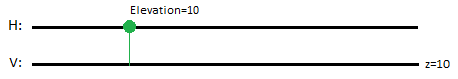
Figure: Vertical design created using a single Elevation rule
(represented in plan perspective above and profile below)
Create a vertical design by adding multiple Elevation rules
If you need a more detailed definition of a VAL, apply many Elevation rules to the same line. The list order is not important, since all rules attached to same line is sorted when computing the VAL for the line, but where you place the rules along the line does affect the vertical geometry.
Note: As shown below, grade breaks will occur at each location where the Elevation rule is applied to a line.
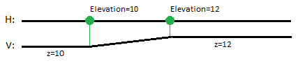
Figure: Vertical design created using multiple Elevation rules
In this example, the first Elevation rule extends the line’s elevation (10.0) to the beginning of the line and the second Elevation rule extends the elevation (12.0) to the end of the line.
To apply an Elevation rule:
- Select the rule.
- Enter an elevation.
- Pick a point along the line (or enter a coordinate).
- Write a description of the rule to help you understand its intent when shown in the rules list.
- To place this rule above the previous (or a selected rule), check the Insert above selected rule box.
- Click the Add Rule button.
Properties
- Description - Name given to the rule. When created, this field is empty (blank). The name or description can be useful, in some cases, for understanding the order of the rules.
- Type - Elevation. This read-only property cannot be edited.
- Source line - Name of the line to which the elevation was applied. If no line is connected, the property is empty (blank). The field is empty if the Search distance is set smaller than the offset distance between the elevation point you specify and nearest line.
- Elevation - Elevation at the specified location of the rule.
- Active - When created, this is set to True. If it is True, the rule is used in computations. Set this to False when you want this rule to be ignored.
- Order - Shows the order of the rule in the rules list.
- Status - Shows a code if there is an error computing the rule (or 0 (zero) if the status is okay).
- Message - If the Status=0, this property is blank. Otherwise, there is a message matching the status code.
