Generate POSPac Position Fixes
Generate POSPac Position Fixes is a method that lets you improve the trajectories of a mission in the Applanix’s POSPac MMS software where there is no GNSS coverage or the coverage is extremely poor. At these locations, trajectories are corrected by measuring the distance between ground control points (GCPs) collected in the field and targets extracted from the acquired scan data. The results of these measurements are Offset values that are projected back to the trajectories. New positions of the modified trajectories are then exported to a text file, which is used by the POSPac MMS software to do a second-pass on the trajectory data.
Prerequisites:
You need to have:
- The POSPac MMS software installed and a valid license for the typical IN-Fusion processing methods.
- The SBET trajectory file processed in POSPac MMS with desired IN-Fusion processing method or the NAVreal-time trajectory in case of POSPac processing not possible.
- Create a VCE project and change the coordinate system to match the coordinate system for the mobile mapping data to import.
- Import the mobile mapping data (*.mxdb) and apply the previously processed corrected (SBET) trajectory or real-time (NAV) trajectory to it.
- Extract the scan data from at least a run (see Generate Scans).
- Import into the project a file (in Shape, or ASCII, or CSV format) containing ground control points (GCPs) in the project coordinate system.
To generate POSPac Position Fixes in Trimble Business Center:
- In the Project Explorer, right-click the Mission node and select Generate Pospac Position Fixes in the context menu.
Note: The Generate Pospac Position Fixes command does not open when you select a mission that does not have at least a single scan generated.
- In the Project Explorer, under the Points node, select a ground control point (GCP).
- In the Generate POSPac Position Fixes pane, click the Add Selection to Control Points button to put the selected ground control point (GCP) in the Control Points list.
- If needed, check the Activate Limit Box option. A limit box is a flat box (in the Planar View) or a 3D box (in the 3D View) used to hide all objects outside the box and to only focus on the target to pick. Resize the limit box to remove potential parasite points over the target.
- In the Control Points list, select a ground control point (GCP). The selected ground control point displays in the Targets panel, and centers in the Plan View window.
At the same time, the Point Cloud Smart Picking window opens. You need to pick in the scan data the center of the target that should match the selected ground control point (GCP). This point is called the Picked Target. The Point Cloud Smart Picking tool lets you select the Picking Type to use (Default, Intersected Plane and Road Mark). After picking roughly a scan point, the software automatically computes the best point and displays that point in editable views.
- Default – Use this picking type to pick a target close enough to the ground control point (GCP) by snapping a point of the point cloud. Do not use this type to create a road mark-, or intersected plane-based point.
- Road Mark – Use this picking type if your dataset contains pavement markings. Select this type to pick a point on a road mark edge line in a point cloud. Start by picking a point in a point cloud roughly near the roadmark edge line for which you want to create a point. The Validate Picking window displays showing an overhead view of the roadmark edge line and the automatically selected pick location, and its 3D coordinates.
If necessary, pick a different location in the Validate Picking window to fine-tune the location of the point on the road mark edge line. You do not have to pick a displayed point. When you are ready, click the Validate button, or press the Enter key.
- Intersected Plane – Use this picking type if your dataset contains e.g. black and white checkerboard targets. Start by picking roughly a point in a point cloud. The software automatically fits a plane in the neighborhood of the picked point, and project the picked point onto it. The Validate Picking window opens letting you select the Type of Target to use. For more information, refer to Register MX9 Mobile Mapping Run Trajectory.
Notes:
- For the Road Mark and Intersected Plane picking modes, you can change the point cloud rendering setting. Gray-Scale Intensity renders the point cloud using a gray scale based on the intensity of each point. Color-Coded Intensity renders the point cloud using a color scale based on the intensity of each point. Color by Distance to Plane renders the point cloud using a color scale based on the elevation information of each point.
- For the Intersected Plane picking mode, you can use the Intensity slider to decrease (or increase) the contrast of a target to pick, especially when the target has some reflective parts.
- The Validate Picking window now includes direct residuals to Ground Control Points (GCPs), helping you choose the optimal target center regardless of the target type. These residuals are updated whenever you modify the templete, such as changing the center of the target (by picking a new center or by moving it with the keyboard arrows (including fine adjustements using the Shift key)) or adjusting the bolt size when selecting a GV Target.
- When you are ready, click the Validate button, or press the Enter key.
The 3D coordinates of the picked target display in the Target field. The distance gaps between the selected ground control point (GCP) and the picked target along the Easting, Northing and Elevation display in the Easting Residual, Northing Residual and Elevation Residual fields.
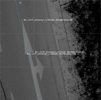
In the Plan View, the picked target has the name of the ground control point (GCP) and the representation shown below (name in blue):
A pair of a ground control point (GCP) and a picked target is enough to perform the PFIX computation. If you wish to use more, do one of the following:
- Select a new ground control point (GCP) from the Control Points list in the Generate POSPac Position Fixes dialog.
- Or click
 to add a new pair pairing line and choose a new ground control point (GCP) from the Control Points list.
If there are more than one pair of ground control points (GCPs) and picked targets in the Targets pane, you can choose a pair to use in the PFIX computation by keeping the pair checked and unchecking the rest.
- If necessary, you can open the Point Cloud Smart Picking window again and change the picked target location by clicking
 .
. - Click Compute. The computation consists in reducing the global error between the ground control point(s) (GCPs) and their corresponding targets.
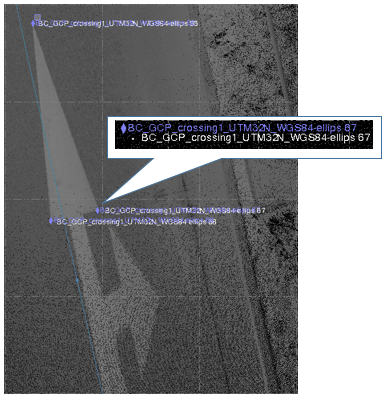
- The updated target has the following name: Mission_Name-PFIX-GCP_Name.
- The software generates a Custom Events file in the PFIX folder under the Trimble Business Center project folder. - If required, open and view the Custom Events file with a text editor.
- Close the Generate POSPac Position Fixes dialog.
- To compute a Smoothed Best Estimate of Trajectory (SBET) file:
- In Trimble Business Center, see Process Raw Trajectory Data.
- In POSPac MMS, see the steps below.
To compute a Smoothed Best Estimate of Trajectory (SBET) File in POSPac MMS:
- Start the POSPac MMS software.
- Create a new project and save it.
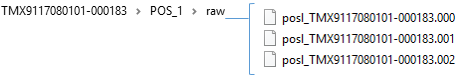
- Locate the folder containing the raw data for the current MX9 project using the Browse icon.
Select the first in the series of POS logged files to extract and then click Import.
The POSPac MMS software sequentially imports the entire series of valid POS logged data files starting from the first file selected.Notes: At the completion of the extraction process and ephemeris download process, a dialog may appear if the POS data does not contain the antenna information.
- If you know the antenna manufacturer and type, enter the information.
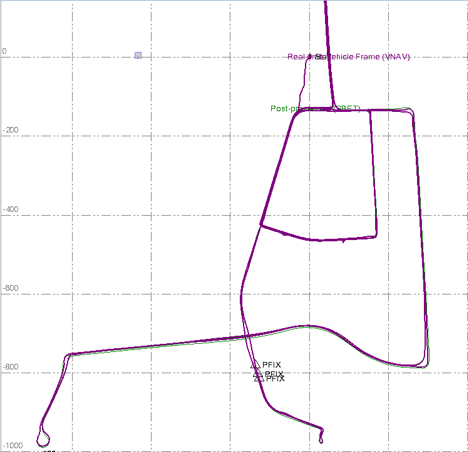
- If you do not know the antenna manufacturer and type, let the software assign a default type.The trajectory (in mauve) appears in the Plan View.
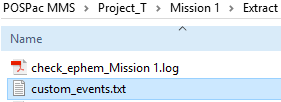
- Copy the Custom Events file previously generated in Trimble Business Center to the Extract folder under the POSPac MMS project folder.
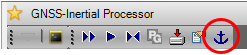
- Click GNSS-Inertial Processor
 to open the pane. The GNSS-Inertial Processor is used to compute a Smoothed Best Estimate of Trajectory (SBET) using the raw inertial, GNSS, and base station data.
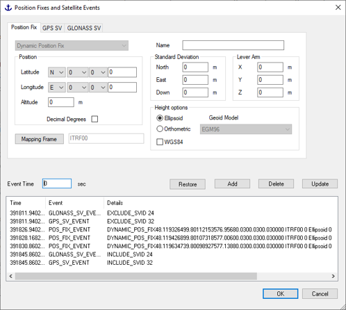
 - Optionally, click Position Fixes and Satellite Events to open the pane.
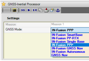
- Select the desired IN-Fusion processing mode from the list.
- Click All Processings.
As a result, the software creates a post-processed Smoothed Best Estimate of Trajectory (SBET) file (in green) in the Proc folder under the POSPac MMS project folder.
To update the scan data in Trimble Business Center:
- In the Trimble Business Center, select the mission from Project Explorer and display its properties.
- Replace the initial trajectory file by the new SBET file computed in the POSPac MMS software with PFIXes.
- Update the scan data according to the new SBET with the Update Scans command.
