Apply Lock and Unlock Rules
Lock and Unlock Rules are 'other' rules used to:
- Lock a segment of a 3D line, thereby preventing you from editing any rules applied to the line; you cannot change the vertical.
- Unlock a segment of a 3D line, thereby allowing you to make edits to rules applied to the line; any previous vertical is ignored, and you can compute a new vertical.
Only one of the rules can be applied to any line at a time (otherwise an error will occur). To apply one of these rules, specify a start coordinate and an end coordinate to any linestring or alignment with a vertical component (makes it 3D). If a Lock or Unlock rule is correctly connected to a line it defines an area where vertical can be changed without losing existing vertical design geometry on other parts of the 3D line (or it conversely defines an area where no changes are allowed, but where the rest of the 3D line can be computed).
By default, all 3D lines included in a vertical design are locked. A property is set to prevent modifying them by accident. If this lock property is disabled for a line, the line can be edited by applying other vertical design rules.
Unlock rule
The rule can be connected to one and only one line. Both the beginning and end points have to be connected to the same line (similar to a Grade rule). When applied between a from station and a to station, the Unlock rule defines the area of the 3D line in which changes are allowed. Areas of the line beyond the extents of the Unlock rule cannot be modified. In theory, many Unlock rules can appear on one 3D line. The Unlock rule is basically used to adjust a portion of a line to handle conflicting situations, like a line intersecting it, etc.
Example where the Unlock rule is useful
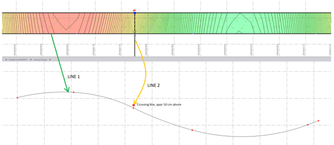
This example shows a T-intersection where two alignments intersect (LINE1 and LINE2 in the illustration). Both alignments are computed separately and have their own verticals. Adding the linework to a surface model causes flags because there are different elevation values at same point. Below, the vertical alignment for LINE1 is shown in the lower view, and the vertical intersect point of LINE2 is shown as a red circle (with the comment “Crossing line, appr 50 cm above”). This situation is common and can be addresses using the rules.
To fix the vertical gap between the two intersecting lines, two rules are needed;
- Connector rule (to copy the elevation from one line to the next)
- Unlock rule (to release an area for computing new geometry)
In this case, LINE2 is unchanged and LINE1 will be changed in an area around the intersection point (some distance before and some after the intersection point). Remember that both lines (LINE1 and LINE2) are 3D lines with their own vertical geometry for which the property Locked=true.
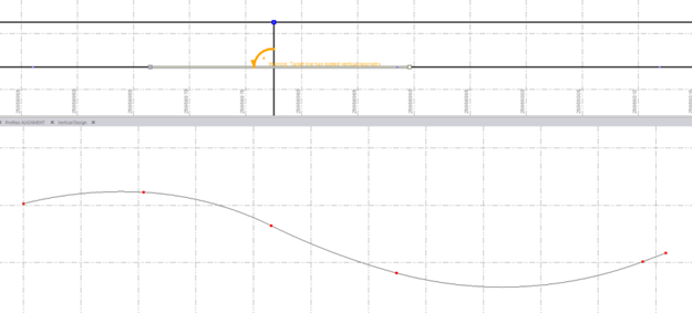
If only the Connector rule is active (copying the elevation from LINE2 to LINE1), the vertical of LINE1 cannot be computed since it is locked. So the vertical alignment will be unchanged and the Connector rule will get a message status=10 (“Warning: Target line has locked vertical geometry”). See the illustration below.
Therefore, you must add an Unlock rule so you can define the area of LINE1 to be released for computation.
Length of the Unlock rule
It is important to be aware of how the length of the Unlock rule works. When the Unlock rule is activated, the original vertical in the rule's area alogn the line is deleted and replaced with the newly adjusted geometry. The only way to re-apply the old vertical (if needed) is by using the Undo command.
Tip: Apply the Unlock rule to a length along the line as short as necessary,and then extend it until the desired result is achieved. By doing this, you prevent removing any vertical geometry that is needed.
In the illustration below, the new vertical geometry in the area of the Unlock rule is shown. The beginning and end points of the Unlock rules are indicated by green circles in both views. The intersection point between them is also shown. In this case, the new geometry is above the original geometry. The original geometry will be deleted as soon as new geometry is computed, and the flag at the intersection point will disappear.
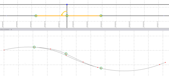
The vertical geometry in the Unlock rule's area is computed with smooth connections between the from and to stations of the rule. The geometry is tangential to the original geometry, both in the beginning and in the end, as well as at the intersection point (to achieve the correct elevation).
It is possible to define many rules inside the area of an Unlock rule. If so, the smoothing goes from the beginning until the first rule that appears, and from the last rule until the end of the Unlock area. In between the first and the last rule, the geometry is computed normally.
The Lock rule
Like the Unlock rule, the Lock rule can be connected to one and only one line. Both the beginning and ending points must be connected to the same line. The rule defines the area (by from station and to station) of a 3D line that cannot be changed. In theory, many Lock rules can appear on one 3D line. The Lock rule is used to freeze a specific area of the 3D line so the rules along the rest of the line can be computed.
Example where Lock rule is useful
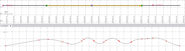
This illustration shows a 3D line with a complete vertical alignment.
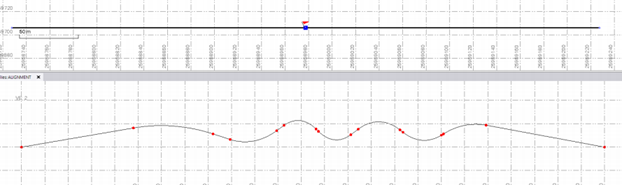
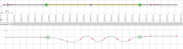
If such a long alignment already has vertical geometry that should not be overwritten, it can be secured by applying a Lock rule. Applying the rule will make the rest of the alignment available to add other vertical design rules as necessary. The illustration below shows how a Lock rule has been applied to secure a specific portion of the alignment.
By adding several rules, the end parts of the alignment can be computed without overwriting the secured area. In this example, two Elevation rules are applied, one at each end part. The green circles shows the range of the Locked area (where the Lock rule is located). Notice that a portion of the line has been 'smoothed' to better connect the vertical geometry between the locked area and the computed area (the smoothing length cannot be changed; it is predefined).
How to merge a locked and an unlocked area
The locked area cannot be changed. Therefore, the unlocked area is where any smoothing will be done to achieve better vertical geometry; all changes must be computed inside unlocked areas. The vertical geometry of the line is computed to be tangential at the beginning and ending of the unlocked area, and to have smooth connections along its length.
To apply a Lock or an Unlock rule:
- Select the rule.
- Pick a point along the line (or enter a Start coordinate).
- Pick a point along the line (or enter a Start coordinate).
- Write a Description of the rule to help you understand its intent when shown in the rules list.
- To place this rule above the previous, check the Insert above selected rule box.
- Click the Add Rule button.
Properties
- Description - Name given to the rule. When created, it is empty (blank). The name or description can be useful, in some cases, for understanding the order of the rules.
- Type - Lock or Unlock. This read-only property cannot be edited.
- Active - When created, this is set to True. If it is True, the rule is used in computations. Set this to False when you want this rule to be ignored.
- Order - Shows the order of the rule in the rules list.
- Status - Shows a code if there is an error computing the rule (or 0 (zero) if the status is okay).
- Message - If the Status=0, this property is blank. Otherwise, there is a message matching the status code.
