Apply an Elevation Line Rule
Elevation line is a ‘point rule’ used to reduce the number of other user-defined rules, such as Connector rules, used to copy an elevation from one line to another while elevating multiple lines from 2D to 3D. To apply it, simply specify a vertical radius and a start coordinate on a source line and end coordinate on a target line. Each line that is crossed between the two lines has an elevation computed at the intersection point (interpolated based on the source and target line elevations. After you apply this rule, you can always edit other associated properties in the Properties pane.
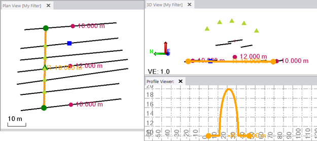
Figure: Source, target, and interseted lines in the Plan View, 3D View, and Profile Viewer
In the image above, the flat section is expected. The two outermost 3D lines intersected by the Elevation Line Rule define the profile. The middle 3D line (at 12.000 m) in between does not contribute to the profile because the profile cannot calculate a slope using more than two 3D lines.
Note: If you do not pick start and end locations exactly on the source and target lines, the start and end points are applied to the nearest perpendicular locations on the line from the point you pick in the view (based on the Search distance setting, which can be accessed by selecting the vertical design and pressing [F11] to open the Properties pane.
Requirements:
- Multiple lines that you want to elevate at once. One or two of the lines should be 3D (elevated); outer lines in a series are best since they establish a direction for the rule's profile.
Notes:
- If many lines intersect the Elevation Line Rule, the outer intersection point defines the rule's elevation. The rule profile's outer range is defined by the lowest and the highest values of intersecting points.
- If an outer line is 2D, there will be no elevation extrapolation, but a status code is given.
- If two points on intersected lines are in the same location, the radius is calculated based on that location. If there is only one intersection point, the elevation is assigned to the start- and end points of the rule.
- If the rule intersects an unlocked 3D line, its elevation will be overwritten by the rule's elevation and the existing vertical will be deleted.
- If the rule intersects a locked 3D line that is not the outer line, it is ignored (the 3D line is not changed and no status code is given).
- If the rule intersects a locked 3D line that is the outer line (defines the elevation to the rule), it can be the source for the rule.
- To prevent any intersecting lines from being computed/elevated by the rule, lock them first.
To apply an Elevation Line rule:
- Enter a Vertical radius that will be used to elevate the intersecting lines to potentially various heights, thereby defining the vertical profile of the rule.
The radius can be zero, positive, or negative. A radius property with a negative value will compute a concave profile. A radius property with a positive value will compute a convex profile.
Note: If the radius is very small (has a short range), it computes as a small bump at the middle of the rule; the location of the bump (if the radius is smaller than the range of the rule's profile) is set to be 0.5 (at the middle of the rule) and cannot be changed.
- Pick a Start coordinate along a 3D line (source line).
Tip: The Elevation Line Rule start and/or end coordinate can snap to an Elevation Point Rule to use those elevations.
- Pick an End coordinate along another 3D line (target line).
- Write a description of the rule to help you understand its intent when shown in the rules list.
- To place this rule above the previous (or a selected rule), check the Insert above selected rule box.
Note: To easily see which intersecting lines the Elevation Line rule has affected, click the Other Settings tab and check the Show Automatic Z Intersection points box.
- To confirm the rule's profile after you close the command, select the rule's line, right-click, and select Profile Viewer.
Properties
- Description - Name given to the rule. When created, this field is empty (blank). The name or description can be useful, in some cases, for understanding the order of the rules.
- Type - Elevation. This read-only property cannot be edited.
- User-defined source line - Name of the line to which the elevation was applied. If no line is connected, the property is empty (blank). The field is empty if the Search distance is set smaller than the offset distance between the elevation point you specify and nearest line.
- Source line - Name of the line to which the elevation was applied. If no line is connected, the property is empty (blank). The field is empty if the Search distance is set smaller than the offset distance between the elevation point you specify and nearest line.
- User-defined target line - Name of the line to which the split was applied. If no line is connected, the property is empty (blank). The field is empty if the Search distance is set smaller than the offset distance between the elevation point you specify and nearest line.
- Target line - Name of the line to which the elevation was applied. If no line is connected, the property is empty (blank). The field is empty if the Search distance is set smaller than the offset distance between the elevation point you specify and nearest line.
- Vertical radius - Vertical radius at given location (VPI) of the rule.
- Active - When created, this is set to True. If it is True, the rule is used in computations. Set this to False when you want this rule to be ignored.
- Order - Shows the order of the rule in the rules list.
- Status - Shows a code if there is an error computing the rule (or 0 (zero) if the status is okay).
- Message - If the Status=0, this property is blank. Otherwise, there is a message matching the status code.
