Extract Overhead Line Features from a Point Cloud
Use the Extract Line Features command to create linestrings from overhead utility lines displayed in a point cloud. The overhead utility line extraction process results in the creation of a matching linestring for each selected utility line.
Prerequisites:
See the Subscription Plans page. For a license matrix by command, see the License page in the TBC Community. Also see View and manage licensed features.
To extract overhead line features:
- Select Extract Line Feature in Point Clouds > Extraction to display the Extract Line Feature command pane.
- In the Extraction type drop-down list, select Overhead Lines.
- Optionally, click the Line Settings drop-down group box and enter a Name and/or assign a Layer, Line style, and Color to the extracted linestrings.
These properties will be applied to all extracted linestrings. However, you can change them for any of the individual linestrings after the extraction process is complete by selecting the Post QA/QC tab, as described in step 12 below.
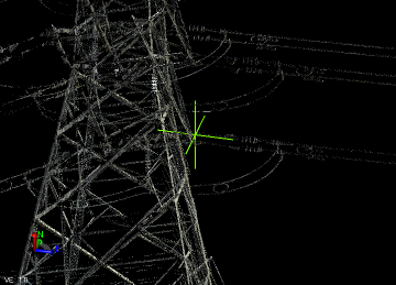
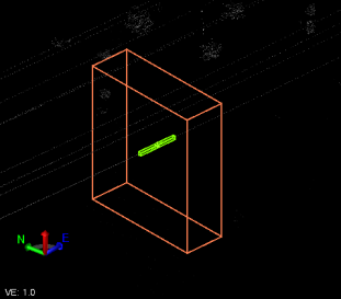
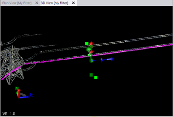
- In the Extraction group box, click in the Start point field and then, in the 3D View, select the starting point for the overhead line you want to extract (for example, where it intersects a pole).
A green icon with intersecting vertical and horizontal lines indicates the line's start point.
- Repeat for the End point.
A purple icon with intersecting vertical and horizontal lines indicates the line's end point.
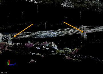
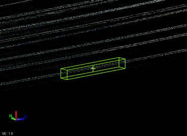
The extraction of any selected overhead line will end at the opposing vertical planes defined by these two points. Note that the start and end points can be anywhere on a line, not just at a tower or pole. And, if the line is somewhat straight (not too much sag), you can have one or more intervening poles between your selected start point and end point, as shown in the following example of extracted lines spanning multiple poles.
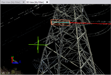
- Click in the Line(s) field, and then, in the 3D View or Plan View, click on an overhead line you want to extract.
A green extraction icon displays where you clicked on the line, enclosed in a green 3D search box. If the Adjacent search check box is checked, an orange 3D search box also displayed.
- To select additional parallel lines located between the Start point and End Point for the extraction process, do either of the following:
- Manual selection - With your cursor still in the Line(s) field, click the additional overhead line(s) you want to extract.
- Automatic selection- This option will automatically select parallel adjacent lines depending on the size you specify for the orange 3D search box. (This can be very helpful if you are extracting many lines as, for example, might be the case with large power towers.)
- If it is not already checked, check the Adjacent search check box to display the orange 3D search box.
- Use the Search size slider control to size the orange search box so that it encompasses all of the adjacent parallel lines you want to extract, or type in a size for the box.
The depth of the orange 3D selection box is determined by the distance specified in the Search length field for the green3D search box . It's height and width are determined by the distance specified in the Search size field.
Be sure to view the lines from different perspectives to ensure all of the lines you want selected run through the box.
- Click the Find button.
Each automatically selected line includes a green extraction icon and is included in the number displayed in the Lines field.
If an adjacent line is missed during the automatic search, you can click in the Line(s) field and select it manually.
The rest of these instructions apply to each of the selected lines.
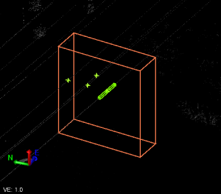
A linestring will be extracted in multiple segments for each selected overhead line, each segment based on the distance specified in the Search length field. The extraction occurs first in one direction from your selection point to the vertical plane at one end of the line, and then in the other direction to the vertical plane at the other end. You might want to select somewhere near the middle of the line between the Start point and End point to more easily view the extraction process, although you can click anywhere on the line to select it.
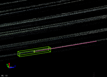
In this example, one overhead line has been selected. The green box graphically indicates the specified Search length and Search width.
Note: If you are using the Adjacent search option, the depth of the orange 3D selection box is determined by the distance specified in the Search length field. It's height and width are determined by the distance specified in the Search size field.
- Optionally, type in or use the slider controls to change the Search length and/or Search width to ensure that your extracted line will be based on the appropriate available scan points.
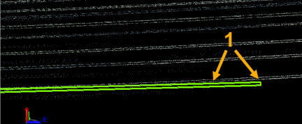
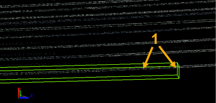
For fastest processing, you might define a search box that is as long as possible (less extraction segments to create) and as narrow as possible (less extraneous scan points to consider) while still being able to capture all of the applicable points as each linestring segment is automatically extracted. However, you must consider how best to handle situations of sparse scan points and non-horizontal (drooping) overhead lines. If the search box is too long or too narrow, each extraction segment may not include all of the points required for the linestring extraction, causing the extraction process to stop (that is, it cannot determine the next best scan points to use to continue the extraction). In this case, the process will prompt you to determine how best to proceed. For example, if scan points for the selected line (1 in the image below) fall outside the green extraction search box, the extraction will stop before completing. In this case, you could change the search width (and/or length) to ensure all targeted scan points lie inside the box along its length.
- Click the Extract button, or press the Enter key.
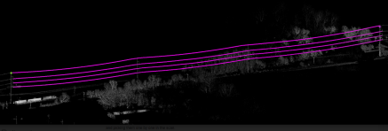
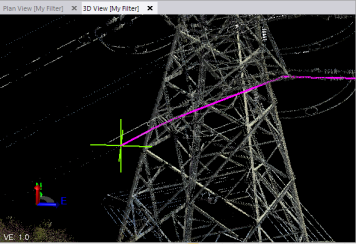
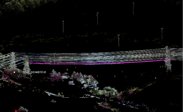
Each extracted line segment is displayed in magenta as it is extracted. The extraction process is first performed in one direction until it reaches the end of the line.
Then it is performed in the opposite direction from the line selection location until it reaches the opposite end of the overhead line. If applicable, it then repeats for each additional line selected.
A progress bar displays at the bottom of the window.
- Do one of the following:
- If your linestrings are extracted successfully, proceed directly to step 12.
- If the extraction process stops, the extraction line turns from magenta to red. Continue with step 11.
- Zoom in on the 3D View to see where the problem is occurring, and do any of the following as applicable to continue with the extraction process:
Note: At any time, you can click the Undo button as necessary to delete previously extracted segments. Or, you can click the Switch Direction button to stop extracting in one direction from the line selection point and start extracting in the opposite direction.
- Make changes in the Search length field and/or Search width field as necessary to capture applicable scan points. Then click Extract.
- Select the the Continue straight option and click Extract to specify that the extraction line continue on its current trajectory path until it is able to identify additional line scan points or it reaches the End point or Stop point vertical plane.
- Select the Select next point option and then, in the 3D View, select the next scan point to use for the continuation of the extraction line. Then click Extract.
Example of use of Continue straight option:
Example of use of Select next point option:
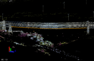
Completed extraction:
- Once extraction is complete, do either of the following:
- Click the Create Lines button to save the extracted linestrings in the project without making any additional changes.
- Select the Post QA/QC tab and do any of the following:
- Optionally, click the Activate Limit Box button and use the limit box to limit the scan points displayed in the view.
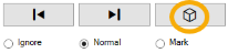
- Use the Forward and Backward buttons to select each of the extracted linestrings to review it. Then, for the selected linestring, optionally select to Ignore it (the extracted linestring will turn red and will not be saved) or Mark it for reference by creating a white linestring.
- Select one of the Smooth Line Options to enhance the selected linestring, or select the Apply to All button to apply the selected smoothing option to all of the linestrings. You can experiment with the different options to determine the one that best fits your needs.
- Change any of the Line Settings for the selected linestring.
When you are done, click the Add All button to complete the extraction process and save the selected linestrings in the project.
- Optionally, click the Activate Limit Box button and use the limit box to limit the scan points displayed in the view.
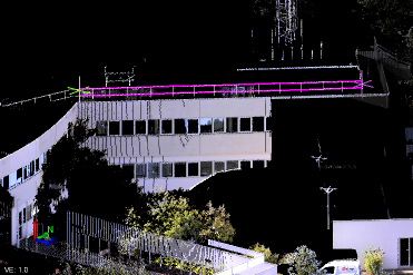
Tip: The Overhead Lines extraction option can be used to extract line features other than overhead utility lines. In the following example, the option is being used to extract lines from a railing atop a building.