Limit the Graphic View
Use the Set Limit Box command to display a customizable planar box in Plan View or a 3D box in 3D View to select the scan points or other objects you want to view; all objects outside the box are no longer displayed in the graphic view. You specify the size, shape, location, and orientation of the limit box using either the Select Limit Box command pane, the controls displayed with the limit box in the graphic view, or a combination of both. Limit boxes are helpful in hiding extraneous objects in the project and providing focus just on that part of the view in which you have interest (for example, a single floor in a multi-floor building).
Although you can display only a single limit box at a time on the Plan View or each 3D View you have open, you can create multiple custom limit boxes with names that you can select to reuse when necessary.
To activate a limit box:
Select Activate Limit Box in Point Clouds > View to toggle between displaying and hiding the limit box in the selected view. If the Set Limit Box command is not already displayed, it is displayed when you select the Activate Limit Box command. The first time the limit box is displayed (activated) in a view, it defaults to including all of the objects displayed in the graphic view. (You may need to zoom out to see the box.)
Once the limit box is active, you can specify its size, shape, location, and orientation to select the data you want to view exclusively. Use either the Set Limit Box command pane or the controls included with the limit box in the graphic view, as described in the next section.
Notes:
- If the limit box is displayed but the Set Limit Box command pane has been closed, you can display the command pane by double-clicking the limit box.
- You can use an active limit box to create a region by selecting the content of the limit box in a graphic view (drag a selection box round it) and selecting Create Point Cloud Region in Point Clouds > Regions (or pressing Ctrl + T). You can also select Rectangle Select or Polygon Select in the Status Bar ![]() (or press F5 or F6) to create a point cloud region within the limit box.
(or press F5 or F6) to create a point cloud region within the limit box.
To edit and, optionally, save a new limit box:
- Select Set Limit Box in Views > 3D View to display the Set Limit Box command pane.
At the same time the Set Limit Box command pane displays, a default limit box displays in the selected view. The first time the limit box is displayed (activated) in a view, it defaults to including all of the objects displayed in the graphic view.
Note: The Set Limit Box command pane also displays when you select Activate Limit Box in Point Clouds > View, if it is not already displayed.
- If you plan to save the limit box to reuse as necessary, enter an appropriate name in the Name field.
- To change the limit box, complete the edit fields as necessary:
- Plan View: Specify box outline color, origin, length/width/height, and Z-axis rotation.
- 3D View: Specify box outline color, elevation, origin, length/width/height, and X/Y/Z-axis rotation.
Optionally, use the the controls displayed with the limit box in the graphic view to change it.
Plan View
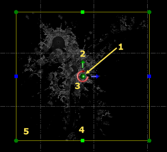
Use click + drag to do the following:
- Move grip (1 above) - Move the limit box in any direction.
- Axis grips (2 and 3) - Move the limit box north/south or east/west. Or, change the Z-axis rotation of the limit box.
- Planar grips (4) - Change the width (green arrows) or length (blue arrows) of the limit box. The origin point changes accordingly.
- Vertex grips (5) - Change the size of the limit box while maintaining the same width/length ratio. Or, press the Ctrl key when using these grips to make sizing changes without maintaining the same width/length ratio.
3D View
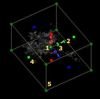
Use click + drag to do the following:
- Move grip (1 above) - Move the limit box in any direction.
- Axis grips (2 and 3) - Move the limit box north/south or east/west. Or, change the X-, Y-, and Z-axis rotation of the limit box.
- Planar grips (4) - Change the width (green markers), length (blue markers), or height (red markers) of the limit box. The origin point changes accordingly.
- Vertex grips (5) - Change the size of the limit box while maintaining the same width/length/height ratio. Or, press the Ctrl key when using these grips to make sizing changes without maintaining the same width/length/height ratio.
- Optionally, use the check boxes to display or hide the various limit box controls in the graphic view.
- Optionally, click any of the following buttons:
- Reset Axis Rotations - Reset the current axis position back to zero (0).
- Fit to View - Refit the limit box to the view (that is, include all objects).
- Create - Save the newly edited limit box so you can reuse it when necessary. Be sure you have first entered an appropriate new name in the Name field. The saved limit box can be selected to use in the Active Limit Box drop-down list in the TBC ribbon.
- Activate/Deactivate -Activate or deactivate the currently displayed limit box.
To edit an existing limit box:
- Select Set Limit Box to display the Set Limit Box command pane.
- In the Limit Box drop-down list, select the limit box you want to edit.
- Make changes as described in the previous procedure.
