Extract Curb and Gutter Line Features from a Point Cloud
Use the Extract Line Features command to create linestrings from curb and gutter features displayed in a point cloud.
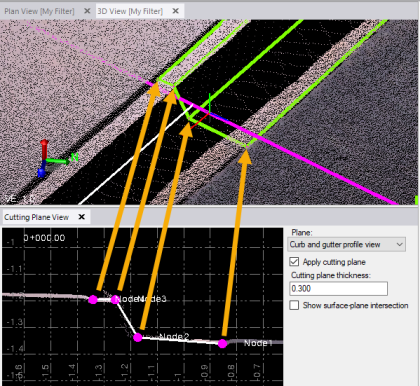
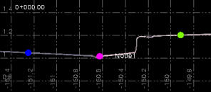
The curb and gutter extraction process results in the creation of multiple linestrings, each based on the nodes that define the cross-section profile view of the feature. The following example shows the cross-section view of a curb and gutter feature being extracted from the point cloud in the 3D View and in the corresponding Cutting Plane View. In this case, four nodes have been defined:
- Edge of pavement (Node 1 in the example below)
- Gutter flow line (Node 2)
- Top edge of curb (Node 3)
- Back edge of curb (Node 4)
Note: The node numbers could be assigned in reverse of this example, wherein Node 1 is the back of curb and Node 4 is the edge of pavement.
Because feature profiles may include curbs, gutters, sidewalks, road barriers, and so forth, you can create up to ten nodes to define the feature profile you want to use to extract lines.
Prerequisites:
See the Subscription Plans page. For a license matrix by command, see the License page in the TBC Community. Also see View and manage licensed features.
To extract curb and gutter line features:
- Select Extract Line Feature in Point Clouds > Extraction to display the Extract Line Feature command pane.
- In the Extraction type drop-down list, select Curb and Gutter.
- Optionally, click the Line Settings drop-down group box and enter a Name and/or assign a Layer, Line style, and Color to the extracted linestrings.
These properties will be applied to all extracted linestrings. However, you can change them for any of the individual linestrings after the extraction process is complete by selecting the Post QA/QC tab, as described in step 9 below.
Next, you will define a cutting plane that will allow you to view a cross-section of the curb and gutter feature. This will enable you to adjust nodes as necessary when the curb and gutter profile changes (for example, a drive way entrance) to ensure you are extracting lines accurately.
- In the Define Cutting Plane group box:
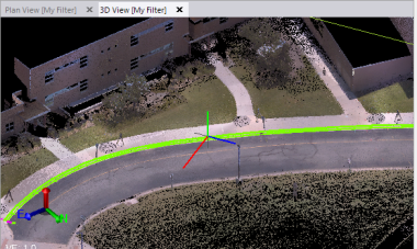
- Click in the Point 1 field and then, in the 3D View or Plan View, select a point on either side of the curb and gutter feature whose lines you want to extract.
- With the cursor in the Point 2 field, click on the opposite side of the feature, perpendicular to the feature, resulting in a perpendicular line that is used to define a vertical cutting view plane.
To reduce the number of unnecessary scan points used for the extraction process, it is important that you create a cutting plane that is perpendicular to the curb and gutter feature.
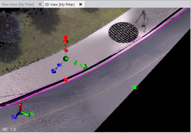
The Cutting Plane View displays showing a vertical cross-section of the selected location on the curb and gutter feature.
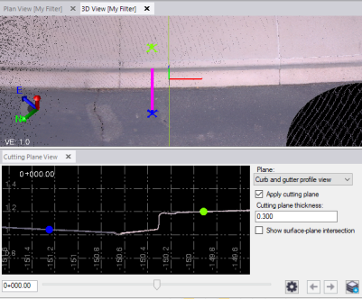
On the Cutting Plane View tab, the Cutting plane thickness defaults to 0.3m. To obtain optimal extraction performance and accuracy, you should select a width that displays the least scan points while still providing the profile line required by the extraction process.
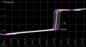
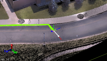
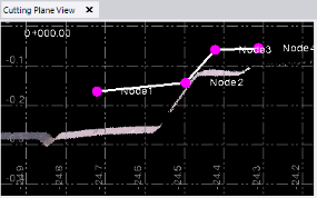
In the following example (with nodes selected), the cutting plane is very thick, resulting in extra scan points that are unnecessary for the extraction process. (A similar situation occurs when you create a cutting plane that is not perpendicular to the curb and gutter feature.)
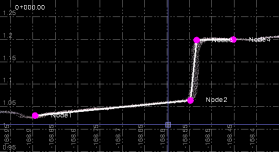
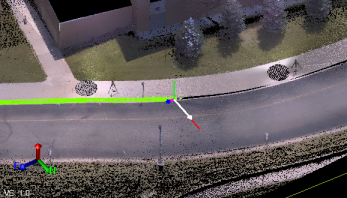
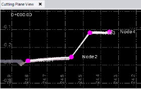
In this next example, the cutting plane thickness has been narrowed, resulting in less, but more than adequate, scan points for the extraction process.
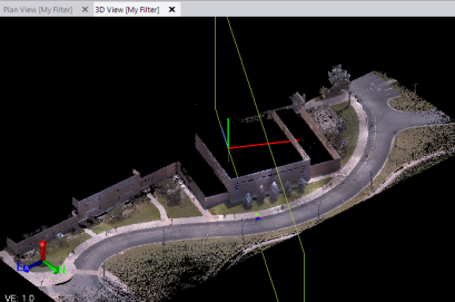
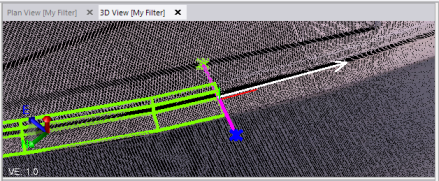
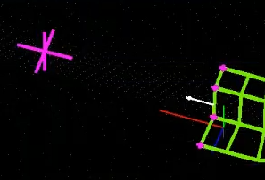
Following is a view of the cutting plane (indicated by a green box) in the 3D View when zoomed out:
The sides of the curb and gutter feature you choose for Point 1 and Point 2 determine the direction in which extraction will first take place, as indicated by the red line.
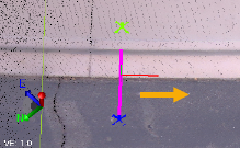
To change the direction, reselect Point 1 and Point 2, or click the Switch Direction button.
You will use the Cutting Plane View to select the location of each of the nodes that will be used to extract the curb and gutter feature linestrings, resulting in a feature profile template.
- In the Curb Pattern group box:
- Select a pattern from the Pattern dropdown list. Note that if this is a new curb pattern, there will only be one option.
- Click in Node 1 and then, in the Cutting Plane View, select the location of the first node.
The first node can be on either side of the curb and gutter feature. In either case, the other nodes will be located in sequence following it.
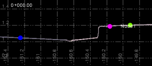
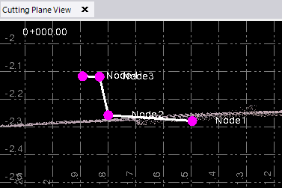
Node 1 (magenta) selected at edge of pavement:
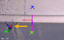
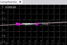
Node 1 selected at back of curb:
- Repeat for the other nodes to complete the definition of your profile template.
In this example, four nodes were defined.
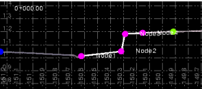
This is the profile template the software will be trying to identify in the point cloud as it attempts to extract the linestrings.
If you need to define more than four nodes, click the Add Node button as necessary to define up to ten nodes.
If you require a node to define the profile template but do not want a line drawn for the node, uncheck the node's Draw checkbox.
To delete a node, click the Remove node button to the right of the node.
- To define a new pattern, click the New pattern button. You can now enter new nodes for a different curb pattern; for example, a driveway, inlet, or pedestrian walkway. You can now switch back and forth between patterns.
- When switching between patterns, the template for the new pattern is automatically moved to the current extraction location. This allows for a continuous extraction process across different curb profiles.
Click Extract to begin the new pattern.
- Use the left and right iteration arrows to move between nodes and edit a specific node.
- In the Extraction group box:
- Click in the Interval field, and then enter or use the slider control to specify the length of each segment to be searched and extracted at a time.
For fastest processing, you might define an interval that is as long as possible (less extraction segments to create). This can work well on long stretches of straight curb and gutter with minimal profile changes, minimal curves, and adequate scan points within the selected interval distance. However, you must consider how best to handle situations of changing feature profiles, curving features, sparse scan points, and so on to minimize how often the auto extraction process stops, requiring your input to help it continue. (You are encouraged to experiment with different Interval values to achieve optimal auto extraction results. In addition, you can change the Interval value any time the extraction process is stopped.)
- Click in the Minimum confidence field, and then enter or use the slider control to specify the minimum "confidence" with which you want the software to identify points correctly.
The higher the value, the more precise the extraction, but the higher the likelihood of the auto extraction process stopping, requiring your input to help it continue. The lower the value, the less precise the extraction, but the lower the likelihood of the auto extraction process stopping. (You are encouraged to experiment with different Minimum confidence values to achieve optimal auto extraction results. In addition, you can change the Minimum confidence value any time the extraction process stops.)
- Click in the Interval field, and then enter or use the slider control to specify the length of each segment to be searched and extracted at a time.
- Click the Extract button to start the auto extraction process.
In the graphic views, each linestring extraction segment is displayed in green as that portion of the linestrings is extracted. A status bar displays at the bottom of the window showing the progress for each extraction.
If there are no problems, the extraction process is performed in one direction from the selected extraction starting point until it reaches the end of the curb and gutter feature in that direction, at which time the auto extraction will stop. You can then click the Switch Direction button and click the Extract button to perform auto extraction in the opposite direction from the extraction starting point.
Optionally, you can click any of the following buttons during the extraction process.
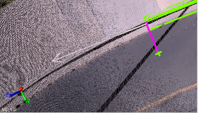
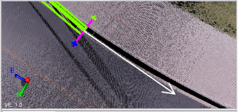
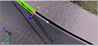
- Stop - Click this button to manually stop te extraction process. When the extraction process is stopped, a white arrow indicates the direction of search for the next segment to extract. You can, optionally, select any of the options described below. Just click the Extract button to continue with the extraction process.
- Finish - When the extraction process is stopped (either because you clicked the Stop button or the process stopped automatically), optionally click the Finish button to end the extraction process and close the Cutting Plane View tab. Click the Add button to save the linestrings created during the extraction process. Or, you can select the Post QA/QC tab and proceed as described in step 9 below.
- Switch Direction - When the extraction process is stopped (either because you clicked the Stop button or the process stopped automatically), optionally click the Switch Direction button to start extracting linestring segments in the opposite direction of the extraction starting point. Then click Extract to continue the extraction in the new direction.
- Undo - When the extraction process is stopped (either because you clicked the Stop button or the process stopped automatically), click the Undo button as necessary to remove the last one or more segments extracted. You may need to do this before proceeding with one of the corrective options described below.
Before clicking the Undo button:
After clicking the Undo button:
If the extraction process encounters a problem that causes the confidence level in correct scan point selection to fall below the minimum you specified in the Minimum confidence field (for example, sparse scan points or change in the curb and gutter profile), the extraction process stops and options are enabled for you to choose to continue. The Extract button, which is disabled during the auto extraction process, is enabled, allowing you to click it to continue extraction process after completing the appropriate option.
If the auto extraction process stops prior to completion in either direction, select the appropriate option below to continue:
- Interval - If the search Interval value is too high, the extraction process might not correctly navigate curves in the curb and gutter feature. In this case, you might want to change the interval to be a smaller distance. Then, click the Extract button to extract the next segment and resume the auto extraction process. As an alternative, you should first consider selecting one of the Additional Options listed below.
- Min confidence - If the displayed Minimum Confidence value is less than the minimum specified in the Minimum confidence field, you might consider lowering the Minimum confidence value. Then, click the Extract button to extract the next segment and resume the auto extraction process. However, because this might not provide the results you expect, you should first consider selecting one of the Additional Options listed below.
- Additional Options:
- Edit template nodes - If the defined template nodes no longer match the curb and gutter feature profile as shown in the Cutting Plane View, select this option and change the location of the nodes to match the new profile. You can do this by clicking each node in the Cutting Plane View to select it (it changes from magenta to yellow) and then clicking a new location. (Also consider using the Apply auto template option.)
Before Edit template nodes:
After Edit template nodes:
- Apply auto template - If the defined nodes no longer match the curb and gutter feature profile as shown above, select this option and click the Apply button to specify that the extraction process automatically detect the new profile and move the template nodes accordingly. Then, click the Extract button to extract the next segment and resume the auto extraction process. (If, after clicking the Apply button, the nodes do not correctly align with the feature, consider using the Edit template nodes option instead.)
Before Apply auto template:
After Apply auto template:
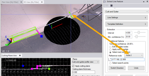
- Select next node point - If the curb and gutter feature profile does not change but scan points are sparse or there are no scan points along a stretch of the curb and gutter feature, or if the feature starts to curve within the specified Interval, you can select this option. Select the node you want to reference, and click past the problem area on the feature corresponding to the selected node. Then, click the Extract button to extract the next segment; click a second time to continue the auto extraction process. (If sparse scan points is the problem, also consider using the Select search points option. If a curving curb and gutter feature is the problem, also consider making the Interval value smaller.)
- Select search points - If the curb and gutter feature profile does not change but scan points are sparse or there are no scan points along a stretch of the curb and gutter feature, or if the feature starts to curve within the specified Interval, you can select this option and click on the curb and gutter feature as often as necessary to help the extraction process navigate past the problem area. Then, click the Extract button to extract the next segment(s) and resume the auto extraction process. (If sparse scan points is the problem, also consider using the Select next node point option. If a curving feature is the problem, also consider making the Interval value smaller.)
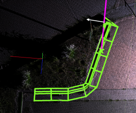
In the following example showing a corner of a curb and gutter feature, the Select search points option was not used, resulting in the extracted lines being too rounded for the actual corner.
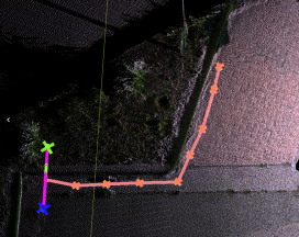
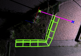
The next two examples show the Select search points option being used, resulting in more accurate lines being extracted.
- Select stopping point - When using multiple patterns, you need to be able to select where a pattern ends so you can begin a new one. Select the point on the linestring where the pattern will change, click the Extract button to extract the next segment(s) and resume the auto extraction process. The extraction process will end at the point selected.
- Edit template nodes - If the defined template nodes no longer match the curb and gutter feature profile as shown in the Cutting Plane View, select this option and change the location of the nodes to match the new profile. You can do this by clicking each node in the Cutting Plane View to select it (it changes from magenta to yellow) and then clicking a new location. (Also consider using the Apply auto template option.)
- Stop - Click this button to manually stop te extraction process. When the extraction process is stopped, a white arrow indicates the direction of search for the next segment to extract. You can, optionally, select any of the options described below. Just click the Extract button to continue with the extraction process.
- When the extraction process is complete, click the Finish button. The Post QA/QC tab becomes selectable.
View of completed linestring extraction:
- To continue, do either of the following:
- Click the Create Lines button to save the extracted linestrings in the project without making any additional changes.
- Select the Post QA/QC tab and do any of the following:
- Optionally, click the Activate Limit Box button and use the limit box to limit the scan points displayed in the view.
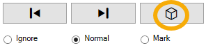
- Use the Forward and Backward buttons to select each of the extracted linestrings to review it. Then, for the selected linestring, optionally select to Ignore it (the extracted linestring will turn red and will not be saved) or Mark it for reference by creating a white linestring.
- To join two lines, click in the Line to join field, then use the Forward and Backward buttons to select the first line. In the Plan View, click the line to join it to. Repeat this process to join more lines.
- Select one of the Smooth Line Options to enhance the selected linestring, or select the Apply to All button to apply the selected smoothing option to all of the linestrings. You can experiment with the different options to determine the one that best fits your needs.
- Change any of the Line Settings for the selected linestring.
- Optionally, click the Activate Limit Box button and use the limit box to limit the scan points displayed in the view.
When you are done, click the Add All button to complete the extraction process and save the selected linestrings in the project.
