Apply a Virtual Break Rule
Virtual Break is a ‘point rule’ used to virtually split a line into sections without physically breaking it (such as would be done by the Break Line command) To apply it, simply specify an elevation, two vertical transition distances from the break point, and a location along the line at which to add the break.. After you apply this rule, you can always edit other associated properties in the Properties pane.
Note: If you do not pick a split location exactly on the line,, the split is applied to the nearest perpendicular point on the line from the point you pick in the view (based on the Search distance setting, which can be accessed by selecting the vertical design and pressing [F11] to open the Properties pane.
The Virtual Break Rule can help you work more efficiently in cases where you want to:
- Reduce the length of the line segment on which you are working, especially if the line is long. Sometimes a line must be divided into sections to make changes within an isolated area.
Example: Splitting a long line to work in smaller sections
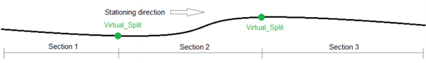
A Virtual Break rule is useful if a line is very long (relative to the range of a virtual design it is participating in). To avoid actually breaking such an alignment into separate segments, splits can be made virtually by applying Virtual Break rules at a certain locations along the line/alignment.
- Compute a vertical alignment on each side of the split point independent of other sections and their corresponding instructions (vertical design rules). Sometimes a line must be divided into sections to isolate the area that will be computed, without needig to actually break the line into smaller pieces. Doing this enables difficult calculations for each virtually split section, thereby providing for seamless continuity between different vertical designs.
Example: Splitting a line so segments are calculated separately
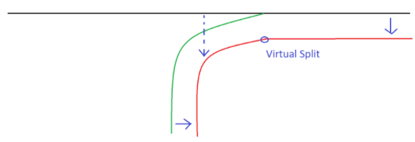
A Virtual Break rule is useful to have the red line computed based on two source different lines (the black and the green).. Therefore, the red line must be split into two separate logical lines by the Virtual Break rule. Then, every virtual part of the red line will be computed separately.
See more examples in Scenarios below.
You can apply multiple Virtual Break rules to a single line. A line with Virtual Break rule applied remains a single, continuous line.
Note: Applying multiple virtual breaks to a line may cause many sections for which a vertical alignment is not computed (see Empty Sections below).
Empty sections
An empty section is a section of a line where no vertical rules are attached. This means that no vertical alignment is computed for this section (it is 'empty'). Nonetheless, entire line must have a vertical alignment along its extents, which means that the vertical for the empty sections must be interpolated.
Example:
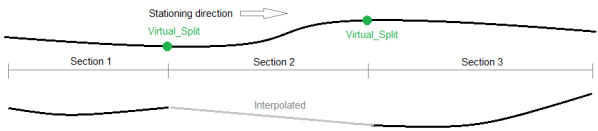
Section 1 and Section 3 are computed with vertical alignments. Section 2 is empty.
Section 2's vertical alignment is therefore interpolated between Section 1 and Section 3, linearly.
See Properties below for details.
To apply a Virtual Break rule:
- Select the rule.
- Enter the elevation of the split point. There are significant differences between entering a value and leaving or entering the elevation as "?" (not a number). See notes below.
Notes on elevations and offsets: The elevation field can be used to force the elevation at the split point to both sides of the line. If no elevation is given for the split point, both sides will appear with different elevations based on the independent instructions (rules) of the separate sides (there will be a vertically step where the split point is located).
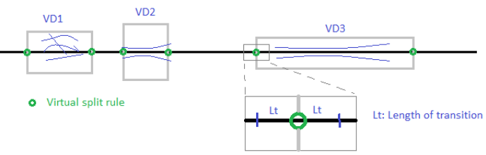
To handle the vertical step, specify Value1 (vertical transition length before split point) and Value 2 (vertical transition length after split point); before and after are defined by the ascending stationing/distance along of the alignment/line.
If a vertical step occurs because no elevation has been specified for the split point, the value 0.01m is automatically assigned for the transitions.
If Value 1 or Value 2 are set to such large values that overlaps occur, computation may be terminated/throw an error.. Normally, these vertical offset values should be small to handle the vertical step issues.
- Enter an offset distance (vertical transition length before the split point) in the Value 1 box. The vertical change is smoothed over that distance. Entering 0.0 means there will potentially be a 'step' (with a length of 1mm) in the vertical.
- Enter an offset distance (vertical transition length after the split point) in the Value 2 box.
- Pick a virtual break point along the line/alignment (or enter a distance along/station value).
- Write a description of the rule to help you understand its intent when shown in the rules list.
- To place this rule above the previous (or a selected rule), check the Insert above selected rule box.
- Click the Add Rule button.
Properties
- Description - Name given to the rule. When created, this field is empty (blank). The name or description can be useful, in some cases, for understanding the order of the rules.
- Type - Elevation. This read-only property cannot be edited.
- User-defined target line - Name of the line to which the split was applied. If no line is connected, the property is empty (blank). The field is empty if the Search distance is set smaller than the offset distance between the elevation point you specify and nearest line.
- Elevation - Elevation at the specified location of the rule.
- Value 1 (vertical transition length before split point) - Shows the offset distance before the split point for the length of the vertical transition.. The vertical is smoothed over that distance. 0.0 means there will potentially be a 'step' (length 1 mm) in the vertical. If a vertically step occur, this property will be assigned the value 0.01 m automatically.
- Value 2 (vertical transition length after split point)- Shows the offset distance after the split point for the length of the vertical transition.
- Active - When created, this is set to True. If it is True, the rule is used in computations. Set this to False when you want this rule to be ignored.
- Order - Shows the order of the rule in the rules list.
- Status - Shows a code if there is an error computing the rule (or 0 (zero) if the status is okay).
- Message - If the Status=0, this property is blank. Otherwise, there is a message matching the status code.
Scenarios
All derived geometry using Cross Slope and/or Cross dZ rules is influenced by a Virtual Break rule (as those rules create a dependent connection between a source line and a target line). The illustration below shows a situation where a source line (black) connects to a target line (blue) by a Cross Slope or Cross dZ rule. The Virtual Break rules (by the split point) on the source line will be inherited by the target line. The blue bullets are computed by perpendicular offset from the source line and intersect with the target line (this target line will be virtually split). Every section on the blue line will be computed independent of the adjacent section; therefore, there will be vertical steps between the sections (see below).
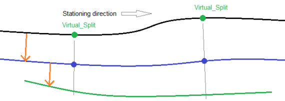
Only Cross Slope and Cross dZ rules can cause these dependencies. Next, the Blue line changes role from being a target line to be a source line when it comes to the second Cross Slope rule. Since there are no Virtual Break on the Blue line, there will be no split on the Green line, even though it is derived from the Blue line. So there are not multiple step dependencies from a source line by using the Cross_* rules to derive geometry. The dependency must be directly connected.
