To extract all of the matching geometric objects in a selected area:
- After selecting Multiple in the Extract Geometry command pane, do either of the following:
- If the CAD shape you want to use as an extraction template already exists in your project, click in the Select shape field and select it in the graphic view.
- If the CAD shape you want to use as an extraction template does not already exist in your project (for example, you want to create the template by tracing a feature in the point cloud using a polyline), click the Create Shape button to display the Create Polyline command pane. Then, create a closed polyline of the desired shape and size. When you are done, the new closed polyline is automatically selected in the Select shape field in the Extract Geometry command pane.
Note: You can use any CAD command in TBC to create a closed-shape template and then select it using the Select shape field.
- To allow specific variations to matching shapes found during the extraction process, optionally check the Include mirrored shape check box and/or Include rotated shapes check box.
- Do either of the following:
- If a polygonal border already exists in your project around the area from which you want to extract geometry, click in the Select the area of extraction field and select it in the graphic view.
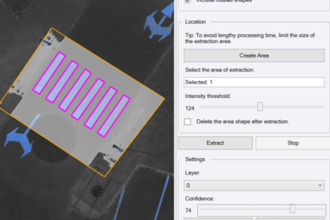
- If an applicable polygonal border does not already exist in your project, click the Create Area button to display the Create Polygon command pane. Then, create a polygon of the desired shape and size to encompass the area from which you want to extract geometry. When you are done, the new polygon is automatically selected in the Select the area of extraction field in the Extract Geometry command pane.
To avoid unexpected results, try to limit the size of the area of extraction to exclude other markings.
- Use the Intensity threshold slider control to adjust the intensity of the point cloud as necessary to best delineate the shape of the features to be extracted.
- Optionally, check the Delete the area shape after extraction check box if, after the command is complete, you no longer need to keep in your project the polygonal border you created to specify the extraction area.
- Click the Extract button to start the extraction process
The progress of the extraction is displayed in the TBC window Status Bar. To stop the extraction process at any time, click the Stop button.
If the results are not satisfactory, try either or both of the following:
- Use the Intensity threshold slider control to change the Intensity threshold level and re-run the extraction.
Following is an example of the results using an Intensity threshold level that is too low.
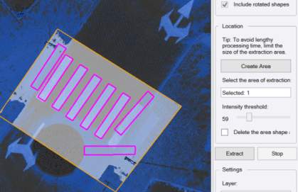
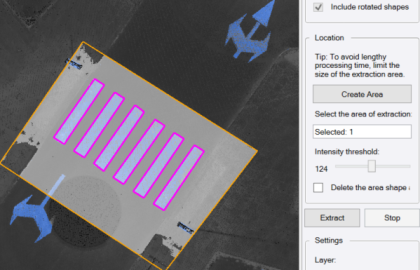
The next example shows better results with a higher Intensity threshold level.
- Use the Confidence slider control to adjust the extraction Confidence level, possibly identifying more matching shapes, or less.
Following is an example of the results using a Confidence level that is too high.
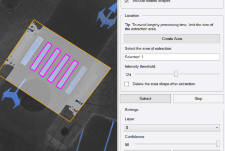
The next example shows better results with a lower Confidence level.
- Use the Intensity threshold slider control to change the Intensity threshold level and re-run the extraction.
- Optionally, in the Layer drop-down list, select a different layer on which to display the newly extracted geometry, or select to create a new layer.
Optionally, to remove all of the extracted polylines, click the Discard button.
- Click the Add button to add the extracted geometry to the project.
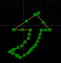
In the following example, a closed polyline was drawn around the lane turn arrow on the right (selected). With the Include rotated shapes check box checked, the template shape was then used extract the geometry (linestrings) for the two arrows on the left.
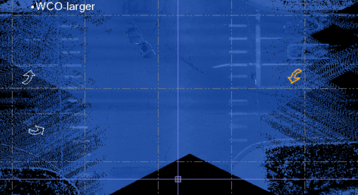
On closer inspection, you can see the closed linestring that was automatically created around a "found" arrow shape matching the shape template.