Work Order Options
Use these options to create a work order, instructing field crews what tasks to perform at a job site, as well as specifying the job site design, tolerances, and other settings to use. They are available in the Work Order Editor.
Options with an * in the dialog are optional for one of these reasons:
- There is a default setting in the Site Controller Software (SCS). Specify a setting to override the default, and the field engineer will not be prompted to choose one.
- The selected task is Multiple tasks, so all options are displayed, but may not be needed for the actual task. If you do not specify a required setting, the field engineer will be prompted to do so.
Tip: To set tolerances, continuous measurement settings, and the coverage map grid size to a suggested default value, click in the option's box, and click .
Warning: Work orders are not backward compatible between SCS900 version 3.0 (v3) and versions prior to 3.0. (v2). Once you assign a work order to a v3 controller, you can no longer assign it to a v2 controller. The only exception to this is when you assign a v2 work order to the Unassigned controller. If you need to assign a v2 work order to another controller temporarily, before you assign it to another v2 controller, use the Unassigned controller.
|
Options |
|
|
Work order |
|
| Name |
This displays the name of the selected work order. |
| Job site name |
This shows the name of the site with which the work order is associated. |
| Controller name |
This shows the controller to which the work order is assigned. |
| Work order task |
See the Types of work order tasks section in Workflow for Managing Work Orders. Note: The option Multiple Tasks shows all of the possible work order settings. |
|
Job Site Designs |
|
| Design |
Design - Select the design that supplies the required data for this work order. Note: Only designs assigned to site controllers appear. |
| Surface offset |
Enter the offsets that can be applied to a surface in the design, in order to create a different surface. If the field crew, in order to create a different surface, must measure a surface that is offset from the surface specified in the design (above), enter the offset measurement. Once you have entered the surface offset, indicate whether the offset is applied by raising or lowering the surface by the specified amount: Above - Select this if the offset surface should be above the surface specified in the design. Below - Select this if the offset surface should be below that surface. |
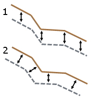
| Offset type |
Vertical - Select this if the surface is to be vertically offset from the design surface (1 in the graphic below). Perpendicular - Select this if the surface is to be offset perpendicular to the design surface (2 in the graphic below).
|
| Underlying surface design |
For a material thickness check, select the design that contains the underlying surface. The underlying surface is the upper surface of the material on which the material of interest has been placed. In most cases, this will be a previously measured surface. To compute the material thickness at each measured point, the site controller software compares the surface measured by the field crew against the underlying surface. Note: Only designs assigned to site controllers appear. |
|
Work order status |
|
| Status |
Select the status that reflects the work order's current state of completion. |
| Priority |
Select the priority that reflects the relative importance of the work order. |
| Due date |
Click the arrow to display the calendar. Select the work order completion date. You can also enter the date in any valid alphanumeric format. The date will automatically be converted to the date format set in your Windows® operating system. |
| Instructions |
Enter any instructions you have for the field crew. |
|
Surface grade tolerances |
|
|
|
Set these tolerances to check a surface grade against a design surface if the selected task requires or allows measurements to be taken. An example of this is grade checking. |
| Above design by
|
Enter an amount (tolerance) that the finished surface can be above the elevation that is established by the design. Note: The default setting in most boxes is "?", indicating that no tolerance has been specified. If you enter a tolerance outside the allowable range, you will need to correct the value. |
| Below design by |
Enter an amount (tolerance) that the finished surface can be below the elevation that is established by the design. |
|
Material thickness and allowable tolerances |
|
|
|
Set these tolerances if the selected task requires or allows measurements to be made in order to check the thickness of a material. |
| Thicker by
|
Enter an amount (tolerance) that the measured thickness of a material can exceed the design thickness. |
| Design thickness |
Enter the intended thickness of a material lying beneath the surface that is to be measured. |
| Thinner by |
Enter an amount (tolerance) that the measured thickness of a material can be less than the design thickness. |
| Measured |
Vertically - When material has been placed on a previously measured surface, select this to compute the material thickness as the difference in elevation between the measured surface and the new surface. Perpendicular - When material has been placed on a previously measured surface, select this to compute the material thickness using a perpendicular projection from the measured surface to the new surface. |
|
Reference line offset from source line |
|
| Horizontal offset |
Select Left or Right for the direction of the offset from the source line. |
| Vertical offset |
Select Above or Below for the direction of the vertical offset from the source line. |
|
Coverage map |
|
| Grid size |
Enter the size of the grid cell for the coverage map that is to be displayed on the controller. Enter the size in the units used at the site. For example, if a project is in meters, a value of "10" equates to a cell that is 10 meters square. |
|
Continuous measurement settings |
|
|
|
Set these values if the selected task requires or allows continuous measurements to be taken, either from a vehicle or when walking. These settings determine how often measurements are taken when the site controller software is used in Continuous measurement mode. |
| Distance interval
|
Enter a horizontal distance, in the units used at the site where the work order will be completed. Every time the receiver (or survey rod) detects that this change in distance has taken place, a point is recorded. |
| Elevation change |
Enter an elevation change, in the units used at the site where the work order will be completed. Every time the receiver (or survey rod) detects that this change in elevation has taken place, a point is recorded. |