Create and Edit Drafting Data
The Drafting toolbar, which is accessible from the Design Data Packages pane in the 3D Viewer, enables you to create and edit simple drafting objects in your model. These features empower you and others (e.g., field staff and contractors) to do basic drafting and make design edits directly, reducing reliance on complex, external software; this ultimately improves project efficiency, reduces dependency on engineering firms, and allows real-time adjustments in response to unanticipated field events or design errors.
-
Create basic, geometric objects, such as points, lines, polylines, rectangles, polygons, and circles directly within an existing design.
-
Select, edit, and remove objects in the view to correct mistakes, adjust elevation, or shift entire designs. Revise your model using simple drag-and-drop functionality.
-
Precisely place objects using snaps and coordinate entry.
-
Publish your design changes to devices in the field.
Prerequisites
-
WorksManager Pro license
-
Project data
-
Project editing permissions
Pick Precisely with Snap Modes
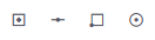 When in Drafting mode, toggle one or more icons to enter snap modes:
-
 Snap to faces - A snap indicator appears on the nearest face, letting you pick it precisely.
-
 Snap to lines - A snap indicator appears on the nearest line or polyline, letting you pick it precisely.
 -
 Snap to points - A snap indicator appears on the nearest point, letting you pick it precisely.
 -
 Snap to center - A snap indicator appears at the centroid of the nearest shape, letting you pick it precisely.
Create Drafting Objects
-
On the left side, click the
 3D Viewer icon.
 -
Click the
 Data Packages icon on the left side.
 -
Expand the design category and select a design you need to edit.
-
Toggle the
 Visibility icon for the design.
 -
Click the
 More icon next to the visible design and select Edit to enter the creation mode. You can only edit one design at a time.

-
Click an icon to create:
-
 Points - Pick a location in the view.
 -
 Lines/polylines - Pick two or more vertex locations in the view to create the line segments between them. Double-click the last vertex to finish the polyline.
 -
 Rectangles - Pick two corners to create one side of the rectangle. Then drag out and click an opposite corner to create the other side.
 -
 Circles - Pick the center point of the circle, drag out, and release to create the diameter of the circle.
 -
 Polygons - Pick three or more vertex locations to create a closed shape. When creating a polygon/closed shape, you can use:
-
Join Start to End - Close a shape using the join operation to connect the start and end points.
-
3D Polygon Drawing Close button - When creating a polygon in the 3D view, a Close button appears once three or more points are placed. This allows you to complete the shape easily without needing to re-select the initial point.
-
Polygon Auto-Closure function - Placing an intermediate point in close proximity to the start vertex now triggers an automatic closure of the polygon, omitting any remaining points.
-
-
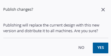
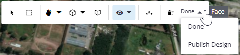
Click Done or Publish Design on the upper toolbar when you are done. Publishing changes replaces the current design with your new version and distributes it to all assigned machines.
 Delete All Design Changes icon to revert to the original state before your edits.
-
Use the selection mode to check your drafting additions. When you have an object selected, the Properties pane shows the object’s attributes, including layer, color, linetype, lineweight, opacity, as well as metadata like area, perimeter orientation, center coordinates, vertex coordinates, and geometric distance and length.
Edit Drafting Objects
Click-and-drag or join and split lines to edit objects.
-
On the left side, click the
3D Viewer icon. -
Click the
Data Packages icon on the left side. -
Expand the design category you need to edit.
-
Toggle the
Visibility icon for a design package. -
Click the
More icon next to the visible design and select Edit to enter the creation mode. You can only edit one design at a time.
-
Toggle the
 Single selection mode on the toolbar near the top of the screen.
 -
Toggle any snap modes you need for editing.
-
Pick an object in the view and make the needed changes.
-
Click Done or Publish Design to exit the editing mode:
- Done- Exits the edit mode; data changes are temporarily stored, but not sent to the field.
-
Publish Design - Creates a new version of the design and dispatches it to the field.
Click-and-drag
To modify an object, click-and-drag:
-
a point
-
vertex of a line, polyline, polygon, or rectangle
-
center point or edge of a circle
Join and split
To modify a linear object, click an icon to:
-
 Join lines - Using the Line Snap mode, pick the end or mid point of one line and then another line's end or mid point. A highlighted preview of the joined lines is shown when you hover over the second line. A segment is created between the points you pick. If the selected lines are touching at their endpoints, they are joined to form a single line. You can also close a shape using Join Lines to connect the start and end points of the same line.
 -
 Split a line - Pick anywhere along a line/segment to add a vertex, thereby splitting the line/segment at that location.
-
Click Publish on the upper toolbar when you are done. Publishing changes replaces the current design with your new version and distributes it to all assigned machines.
-
Use the selection mode to check your drafting edits. When you have an object selected, the Properties pane shows the object’s attributes, including layer, color, line type, line weight, opacity, as well as metadata like area, perimeter orientation, center coordinates, vertex coordinates, and geometric distance and length.
Edit a Point
-
Pick any point measurement in the view.
-
Drag-and-drop it to update its location and coordinates.
-
In the Properties pane on the right, click the Style tab.
-
Select a new color or symbol for the marker in the view.
-
Click Done.
Remove objects
-
Select one or more objects (by pressing Control while picking).
-
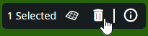
Click the Delete icon on the floating toolbar.
Create a Surface
You can create a surface from selected objects. The created surface appears in the Layers pane, can be sent to machines with other design data, and selected for guidance on machines.
-
Click the
Data Packages icon on the left side. -
Expand the design category you need to edit.
-
Toggle the
Visibility icon for any design packages that contain objects you want to use in the surface. -
Toggle either selection mode to pick objects you want to make the surface from. The number of objects selected is shown on the toolbar at the bottom of the view.
-
Click the Create Surface icon on the same toolbar. A confirmation message appears when the surface is created.
-
Once created, the new surface appears in the Layers pane. Pick it in the view or click the
More icon and choose Select surface to edit its properties in the right pane. -
Click Publish on the upper toolbar when you are ready. Publishing changes replaces the current design with your new version and distributes it to all assigned machines.
Edit a Surface
In the Surface Editor, you can:
-
See details like the count of triangles, vertices, and objects that make up a surface.
-
Add and remove objects that comprise the surface.
-
Rename surfaces and change their colors.
-
Delete surfaces.
-
Click the
Data Packages icon on the left side. -
Expand the design category for the surface you need to edit.
-
Toggle the
Visibility icon for a VCL design surface. -
Pick the surface in the view.
-
Use either selection mode to pick objects you want to make the surface from. The number of objects selected is shown on the bar at the bottom of the view.
-
Pick it in the view or click the
More icon and choose Select surface to see details like the number of points, lines and other objects that make up a surface, as well as the number of triangles and vertices in the surface. -
Click the
More icon next to the visible design and select Edit to enter the creation mode. You can only edit one design at a time.
-
Add and remove objects that comprise the surface.
-
Rename the surface and change its color.
Dispatch Design Revisions
These capabilities collectively aim to provide a streamlined, in-app experience for basic design creation and modification, reducing the need for traditional, heavy drafting software.
-
Once you have made design package edits using the steps above, click Publish on the toolbar at the top of the view.

-
Click Yes in the confirmation dialog to push the changes to assigned machines.