Track Cross-sections in CAD Drawings
If the lines that you want to use to Create Stored Cross-sections from CAD Data are disconnected, use the Track Cross-section command to create cross-section lines by tracking and extracting the top or bottom-most levels from multiple lines on CAD-derived, cross-sections drawings.
The Track Cross-section command works in the Sheet view where the units may be in either inches or mm and distances are very small as compared to Plan View where the units are in feet or meters and the distances much larger.
Note: When entering distances into Sheet View controls, you should enter the values as, e.g., 0.04” so that it converts into correct distances.
|
|
|
|
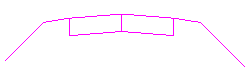
Separate CAD lines representing two cross-section levels |
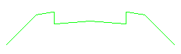
Tracked and extracted lowest level cross-section |
Prerequisites:
- License; See the Subscription Plans page. For a license matrix by command, see the License page in the TBC Community. Also see View and manage licensed features.
- Cross-section drawing containing one or more surface cross-sections
To access the command:
- Select Track Cross-sections in Corridors > Cross-Section.
To track cross-sections in CAD drawings:
- From the Cross-section lines box, pick or window around the individual lines in the Plan View that you want to join into a cross-section, or click Options and choose a selection method from the context menu.
Note: You can select multiple cross-sections at the same time.
- Select a Top or Bottom Track option to specify whether to create a new line along the highest or lowest level of the selected cross-section lines.
- Select the layer on which you want the tracked line to reside in the Layer box, or select <<New Layer>> to create a new layer for the line.
Note: You should select or create the layer that corresponds to the surface's cross-sections that you are creating, e.g. Original ground or Finished design.
- To ..., specify a distance in the Join tolerance box. This tolerance is used to group data elements from the source data into packages that are then analyzed to find the top or bottom surfaces. This is the maximum allowable distance between the end points of lines that will be then selected to form a section.
- In the Gap closure tolerance box, specify the distance that line ends will be extended to close unintended gaps in the cross-section lines. This tolerance is the maximum allowable gap between the end points of lines that will assume to be joined when running the command to find the Top or Bottom surface.
Note: The two tolerances above are not intended to find large gaps, but rather small gaps that are typically found between end points of lines in CAD data, e.g., 0.1’ (depending on the scale of the sectional data being analyzed). Setting this tolerance too high can cause undesirable results.
Note: The Gap Closure Tolerance will not resolve the gap between a closed polygon and the endpoint of another line, only between the end points of lines. The tolerance also will not resolve significant gaps between areas of the same cross-section that have no surface data in the gap. You will need to process the two parts individually in some cases. In some cases, you may need to first close gaps manually using Create Polyline where there are gaps between parts of a cross-section. - Click Apply. The new line is created.
- Use the Create Stored Cross-sections from CAD Drawings command to create a stored cross-section from the new line at the appropriate station along an alignment.
- To edit stored-cross sections, select one, right-click, and then select Edit. The cross-section will be shown, along with a listing of all of the offset and elevation nodes of the cross-section. You can then go to the next or previous cross-section.
