Create Cross-sections from CAD Drawings
Use the Create Stored Cross-sections from CAD Drawings command to create stored cross-sections or 3D lines by automatically extracting them from multiple imported cross-section drawings. The resulting stored cross-sections/3D lines can then be used to quickly build a road surface.
Setting Elevations for Cross-section Conversion
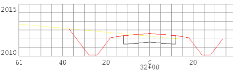
Set the elevation of a grid line - You can change the elevation of an elevation grid baseline to the elevation of the grid line in case there are no elevation labels that can be used. The CAD cross-section conversion process looks at the elevation of the grid lines to see if there is one that can be used to define the base elevation. In this case, you should also use the No Grid option (one elevation grid line and one offset grid line) along with a horizontal and vertical scale to convert the data (see Set a Line Elevation.)
Set an elevation of zero - You can change the elevation of the 0 offset grid line to 0 elevation. The CAD cross-section conversion process looks for an offset grid Line with elevation 0 to determine where the cross-section goes in relation to the selected centerline.
Note: If the lines that you want to use to create stored cross-sections/3D lines are disconnected, connect them using the Join Lines command. If you want to use a cross-section created by the upper or lower-most line segments out of several lines, use the Track Cross-section command to create a single line.
Warning: The stored cross-sections/3D lines created by this command are only as good as the source data in the CAD drawing; check them carefully before using them in a surface.
Note: You will likely want to run this command once for each surface depicted in the cross-section drawings. Each time, you should select or create the layer that corresponds to the surface's cross-sections that you are creating, e.g. Original ground or Finished design.
Prerequisites:
- License; See the Subscription Plans page. For a license matrix by command, see the License page in the TBC Community. Also see View and manage licensed features.
- Horizontal alignment (HAL) along which to create the cross-sections
- CAD data in the form of cross-section drawings containing one or more surface cross-sections, labeled grid lines, and station labels
To access the command:
To extract cross-sections from a CAD drawing:
- Use the View Filter Manager, Select by Layer, and Properties pane to ensure that the cross-section lines, station text, grid lines, and grid text are each on separate layers and include all of the needed objects.
Tip: You might want to open and move a second Plan View and a 3D View so that you can see the extents of the alignment and all grid sheets in one view and a single grid sheet in the other. That way, when you select by layer in the view of the single grid sheet, you can confirm the selection in all of the grid sheets. Or you can use one view for the cross-section drawings and to view the alignment, cross-sections, and resulting surface.
Tip:You may also want to use the Advanced Select command and the Selection Explorer to select all text objects with a "+" and change their layer in the Properties pane. - In the Cross-sections per sheet list, specify whether each drawing shows more than one cross-section on the same sheet.
Note: Select No Grid when there are no grid lines in the drawings. You will need to specify the vertical and horizontal scales for the data later. Also , see the tip below.
- Select the alignment along which to create the cross-sections in the Alignment list. If needed, select <New> to create an alignment.
- In the Maximum grid text distance from grid box, specify the maximum planimetric distance that the offset and elevation text labels are from the grid lines (see Options below).
Tip: In most cases, this setting applies to elevation or offset text around a cross-section grid. However, if you are using the Cross-sections per sheet setting of No grid, the setting can also be used as a buffer zone to extend the influence of the grid lines on the selected data. For example, if your cross-section linework is below the horizontal grid line and below the lower end of the vertical grid line, and the tops of the section lines are above the top of the vertical grid line, you may think that (because all or part of the line is outside the extents defined by the grid) you have to extend all the grid lines, but you do not. You can, in fact, simply enter 100' as a maximum text offset (if there is room around each section). This has the effect of extending the grid lines by 100' above and below the maximum limits of the vertical line and 100' left and right of the ends of the horizontal grid line. Note that this approach works well only if you have enough space between the sections (use an appropriate offset to work within the available space).
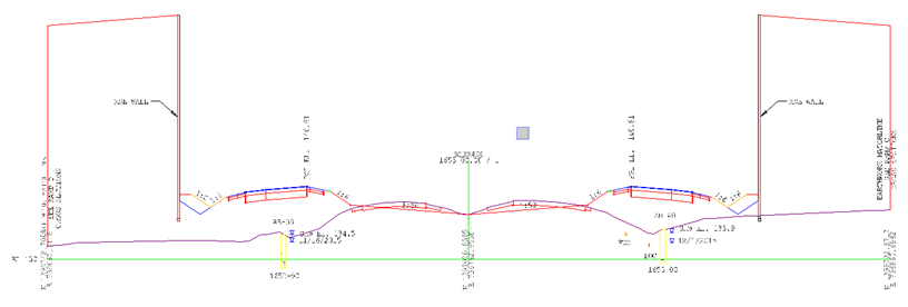
Example 1 - The green vertical line at offset 0 is too short to pick up the tall walls on left and right sides of the road - use the text offset to address this issue or extend the green line so that its top is higher than the highest point in the section
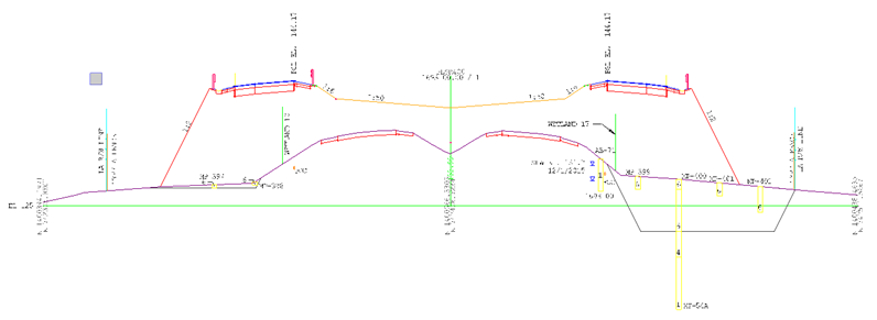
Example 2 - The vertical geen line at 0 offset is only above the horizontal green grid line. The section includes overexcavation areas (grey) and borehole logs (yellow) below the horizontal grid line. Use the text offset value to account for the increased search area or extend the green grid line above or below its current limits using the Trim/Extend command on lines so that it is further above or below any object in the section that you want to convert.
- For the Station Text Location, specify whether the station labels lie above or below the grids to which they apply.
- If you selected None in the Cross-sections per sheet list above, type the value of the Vertical scale and Horizontal scale of the drawing into the appropriate boxes. For gridless data, coordinates are usually shown for the endpoints of the cross-section lines; or there might be one horizontal and one vertical grid line.
- In the Create Options group, select whether you want to create:
- 3D lines - Select this to save time when you want to create 3D lines to add directly to a surface. Converting to 3D lines will generate better, more comprehensive results faster. This conversion of CAD data can be done from either the Sheet View or the Plan View, using the same workflow saving you a lot of time converting linework into 3D models.
- Cross-sections - Select this to create stored cross-sections that you can connect to each other form a road surface. See Connecting Stored Cross-sections below.
- If you selected the Cross-sections option, select the Layer on which you want the cross-sections to reside, or select <New Layer> to create a new layer in the Layer Manager (which will open floating).
- Choose an option in the CAD Data group. You can select various types of data, e.g., station labels, grids, and grid labels by layer, or linework from any layer by selecting objects when converting CAD data into cross-sections.
- Specify layers - Choose this to specify the lines and text to extract by selecting their layers in each list or by picking representative objects in the Plan View. If you chose Specify layers:
- From the Cross-section lines box, pick a road cross-section line (e.g., subgrade) in the view.
- From the Station text box, pick a station label in the view.
- From the Grid lines box, pick a line in the cross-section grid in the view.
- From the Grid text box, pick an elevation or offset labelin the view.
- In the Data source list, select the view from which you want the command to extract the rest of the objects needed to create the cross-sections/3D lines.
- Select objects - Choose this to pick individual lines and text objects to extract. You can also click the By Layer icon on the pane's toolbar to select all other objects on the selected object's layer when you pick it. If you chose Select objects:
- As you pick objects to include, scan each of the grid sheets in the Plan View to make sure that all of the intended cross-section lines are selected and that no unneeded lines are selected.
- Select mixed- Choose this to pick some cross-section lines individually and others by layer. If you chose Select mixed:
- Pick station text, grid lines, and grid text by layer as you did in substeps a - e above.
- Specify layers - Choose this to specify the lines and text to extract by selecting their layers in each list or by picking representative objects in the Plan View. If you chose Specify layers:
- Click Apply. The number of cross-sections/3D lines that were created is reported under Results. The number of grids without valid cross-section lines are reported as well.
- If desired, click Create Surface to build a 3D model from the 3D lines you just generated.
- Select the layer for the next road surface (e.g., milling) and repeat steps 8 - 10 for that layer's set of lines.
- If needed, add the stored cross-sections or 3D lines to a surface using the Add/Remove Surface Members command.
Options:
- Maximum grid text distance from grid - In the Plan View, pick the edge of the grid nearest to the furthest text label. Then pick just beyond the extents of the label. In the example below, the offset label for the grid is the furthest text that you want to associate with the grid.
Note: The text is measured by its insertion point. To find the most accurate distance, use the Measure command. Within that command, use the Insertion Point Snap on a sample grid label, and then a Perpendicular to Line Snap on the adjacent grid line. This needs to be done on at least one offset label and one elevation label; the larger of the two measurement units used. The command will work if the number entered here is exactly the measured distance, but it is advisable to enter a value that is somewhat larger.
When the sheets or grids are too close together it can be ambiguous as to which grid the text is associated with. In these cases you may need to move the grids.
Tip: Stored cross-sections can be hard to select because they do not show up in the Project Explorer. One way to select them is by layer. If needed, use the Selection Explorer to remove other types of objects.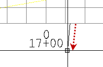
Connecting Stored Cross-sections
The connection type from each stored cross-section to the next cross-section is set in the Properties pane. These connections are only as good as the similarity between each pair of cross-sections; if segments nodes, and labels match from cross-section to cross-section, the connections will be good. After you create and connect multiple cross-sections along an alignment, check the connections!
Scenarios:
- When you create a second cross-section (or more) cross-section along the same alignment, connections are drawn between the nodes on the original cross-section and any corresponding nodes on the new cross-section. You can control the visibility of these connecting lines in the Properties pane for the original cross-section.
- If you import or create stored cross-sections at stations that are beyond the extents of their associated alignment, the cross-sections are denoted by a triangle icon at the beginning of the alignment (the cross-sections themselves are not actually drawn). To select one of the stored cross-sections, ‘window’ around the icon in the Plan View and pick the cross-section in the Selection Explorer.
Note: Select No Grid when there are no grid lines in the drawings. You will need to specify the vertical and horizontal scales for the data later.
Follow these guidelines to make using the command easier:
- Station labels must reside on a separate layer.
- Grid lines must reside on a separate layer.
- Grid text labels must reside on a separate layer.
- Cross-section lines must reside on a separate layer.
- Station labels must be located either above or below the drawing's graph.
