Digitize a Cross-section Along an Alignment
Use the Digitize Cross-section command to quickly 'digitize' (trace) cross-sections in paperspace based on an imported portable document file (PDF) or image files. Then you can bring the cross-sections into your project. Both raster and vector data (if contained in the PDF) can be imported. Vector objects can be detected, highlighted, and automatically traced in the view, if desired.
Typically, you will digitize cross-sections for the purpose of creating a simple road surface for calculating earthwork volumes to bid on a job.
Prerequisites:
- License; See the Subscription Plans page. For a license matrix by command, see the License page in the TBC Community. Also see View and manage licensed features.
- Horizontal alignment (HAL) along which to create the cross-sections
- PDF file or image files with cross-section diagrams that include offset, elevation, and station labels
To access the command:
- Select Digitize Cross-Section in Corridors > Cross-Section.
To digitize a cross-section:
- In the Digitize Cross-section dialog, click Import PDF or Import Images, depending on the type of cross-section data you have.
- If you are importing a PDF, specify the individual pages that you need separated by a comma (2,5,8,9) and/or a range of pages separated by a hyphen (5-9). You can also set the DPI if the PDF is available in a higher resolution.
- Select the first page or image that you want to trace and, if necessary, click either the
 or
or  icon to change the page or image's orientation.
Note: You can also press [Control] and select multiple pages to rotate at once.
Note: If vector data is detected on a PDF page, a tilde icon appears in the upper-right corner of the image preview.
Note: You can press [v] in the Digitize Cross-section from Image dialog to toggle vector data in the image on and off.
Tip: It is often beneficial to start with the cross-section at the lowest station so you can automatically increment the station value as you work from station to station along the alignment (described in step 18). - Click Digitize Cross-section.
- In the Frame Cross-section Grid dialog, use the zoom and rotate tools to fine tune the orientation of the cross-section, if needed. See the Tips section below.
- By default, the Snap to key points box at the bottom of the window is checked so that an icon displays and locations you pick will snap to key points, such as grid intersections, when you are drawing a frame around a cross-section (in the next step). Uncheck the box if desired.
- Pick top left and bottom right points to draw a frame that encompasses all of the offset and elevation data for the specific cross-section you want to digitize first. You can fine-tune the extents of the frame in a few steps.
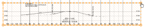
- Click Digitize Cross-section.
Often, cross-sections representing both the existing and design surfaces will appear in the same image. Digitize each of them before moving on to the next station by assigning each to its own layer.
- Click either Existing, Finish, or New Layer to specify the layer on which to place the framed cross-section within the digitizer.
You will map this digitizer layer to a layer in the program in a later step. You can also click New Layer to specify a different digitizer layer (this does not create a layer in the program). Delete any excess layers that you will not use by clicking
 on their tabs.
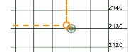
 - Zoom in to the top left corner of the frame and hover over the corner until the hand cursor appears.
- Drag each of the corners until the frame is aligned with elevation and offset lines shown in the background image.
- Type the values for the elevations at the top and bottom of the frame in the Top and Bottom boxes (respectively) at the left side of the screen.
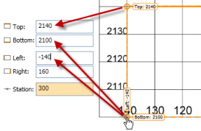
- Type the values for the offsets at the right and left of the frame in the Right and Left boxes, making sure to use a negative number for the left value if that offset is left of the centerline.
- Check the centerline of the frame. If you have the frame properly positioned and referenced in the Elevation and Offset group, the dotted centerline of the frame will be aligned with the zero-offset line/centerline of the cross-section in the background image.
- Type the station value shown for the framed cross-section in the Station box.
- If the subsequent cross-sections that you want to digitize will be at regular increments from the first cross-section, enter that value in the Station increment box. When you digitize the next cross-section, the station will automatically update by this increment.
- Choose digitizing options at the bottom of the dialog:
- Show vector data - Check this box to enable vector data snapping; when you hover over vector data, it will highlight in the view. If you click while it is highlighted, the vector will be traced and connected to the previous point. Press v to toggle this option on and off.
- Snap to key points - See step 6 above.
- Click Publish Settings to map the layers in the digitizer to layers in the program.
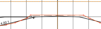
- If you imported vector data and enabled Show vector data, hover over lines in the view and click to trace them. Otherwise, simply start tracing the cross-section for the first layer you specified by picking one end in the view and then picking the other end.
- Pick additional transition points along the cross-section until your tracing and the background match to your satisfaction. See the Tips section below.
Note: Digitized points can be outside of the frame.
- To add labels (such as EOP for edge of pavement) to the nodes along your tracing, right-click any node along your traced line and select a code from the context menu, or select Manage Label Types to create or edit labels.
Note: You can add a label to a node when you create it or anytime afterwards.
- Fine tune your traced cross-section by clicking and dragging nodes you added to better positions and by adding additional nodes.
- If applicable, click the tab for the other layer shown in the cross-section and follow steps 17 - 20 to digitize it as well.
- When you are satisfied with the traced cross-sections, click Finish Cross-section.
Note: The Digitize Cross-section dialog is modeless, so you can switch back and forth between it and the program. This enables you to check the digitized cross-sections in your project at any time.
- Return to the Digitize Cross-section dialog, and repeat the preceding steps to trace additional cross-sections.
Tip: As you digitize cross-sections at multiple stations, check the extents of the frames periodically to confirm their accuracy.
Note: If you find that the elevation or offset of the frames that you are creating are changing by a regular increment, you can right-click on the frame label and select a new incremental elevation or offset from the context menu. - When you are done, delete any sheets you are done with and click the
 icon to close the dialog. Your work is saved and displayed on each PDF sheet or image, so you can easily see where you last stopped working.
 - To view and edit the stored cross-section that you digitized, right-click it in the Plan View and select Edit from the context menu.
Tips on navigating and tracing in the digitizer:
- Click to add new points.
- Click and drag to stream new points; this is not as accurate as adding one point at a time.
- Roll the mouse wheel to zoom in and out.
- Press [Control] and click to copy the frame from the previous cross section.
- Press [Control] and click nodes to erase them, or click and drag existing nodes to new locations.
- Press [Backspace] or [Delete] to erase points/the last segment in the line (in reverse order of creation).
- Resize or reposition the frame by dragging the handles on the corners of the frame.
- Use [Ctrl] + [Z] and [Ctrl] + [Y] to undo and redo point add and remove operations.
- Click and drag using the middle mouse button to scroll the image.
- Right-click to add points with labels (or to manage available labels).
- Press [Spacebar] to move to the next step or cross-section (from any screen).
- If two cross-sections are almost identical, press [Shift] and click to copy and then paste a cross-section.
Connecting stored cross-sections
The connection type from each stored cross-section to the next cross-section is set in the Properties pane. These connections are only as good as the similarity between each pair of cross-sections; if segments nodes, and labels match from cross-section to cross-section, the connections will be good. After you create and connect multiple cross-sections along an alignment, check the connections!
Scenarios:
- If your PDF or image data includes a cross-section split into two images with a match line to show where they connect, create frames around each section as usual. When the program recognizes that the right edge of one frame and the left edge of the other frame each occupy the same offset and elevation for the same station, a dialog will appear and offer choices about how to merge the two to create one cross-section in your project. If you have digitized the cross-section in each frame and have overlapping nodes and segments, the most recent data will over-write the earlier data.
|
|
|
|
|
|
