Georeference a Vector PDF File
Use the Georeference Vector PDF command to geodetically position portable document file (PDF) pages containing vector data, in the Plan View, by correlating the position of specific vector data points with their known coordinates. Like the Georeference Image command, which is typically used for raster images, this command enables you to use imported PDF images as positionally-accurate backgrounds for your data. However, when suitable vector data is available within a PDF file, you only need two known points to georeference the image, whereas the Georeference Image command provides you with a means of performing a least squares adjustment based on the digitizing of a significant number of image pixels representing positions of known coordinates. You can also use this command to edit the position of a sheet that is already georeferenced.
By correlating two vector data points (or pixels) with known coordinates, you can change the planimetric orientation and scale of an image when you compute the transformation.
Note: To use this command, the imported image must contain vector data, at least two points of which occur at know coordinate values.
You can use a rectangular boundary to clip the image (as well as the vector data that may later be extracted). The clipping boundary (shown as a rectangle when you are done) is retained from PDF page to page so it can be modified and at any time.
Prerequisites:
- License; See the Subscription Plans page. For a license matrix by command, see the License page in the TBC Community. Also see View and manage licensed features.
- Imported PDF file containing vector data
- Two or more known coordinates for features that can be correlated with specific vector data points (such as line end points) in the image
- Active Plan View
To access the command:
- Select Georeference Vector PDF in CAD > Images.
- Right-click an imported vector PDF sheet in the Project Explorer and select Georeference Vector PDF from the context menu.
To georeference a vector PDF:
- In the Plan View, zoom or pan to the general area in which you want the image to be located.
- Select an image in the Vector PDF Sheet list. If the list is empty, no PDFs that contain vector data have been imported into the project. The sheet appears in the Plan View.
Note: You can tell which imported sheets contain vector data by the icons in the Project Explorer. Vector sheets appear as
 . Raster images appear as
  .
. - To keep the coordinates of vertices that you can snap to in the vector PDF (indicated by a small x) during georeferencing, check the Save snap locations box. Doing this will enable you to snap to those coordinates using the running Point Snap when the image is in your model (georefeencing is complete). Otherwise, the vertices from the vector PDF are no longer 'snappable' once the PDF is georeferenced.
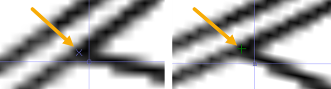
Figure: PDF vector snaps in non-georeferenced PDF and then in the Plan View after georeferencing.
Note: Saving snap locations can result in many snaps, but they are only active when the georeferenced PDF image is visible.
- If desired, check the Apply rectangular clipping box to georeference only a rectangular portion of the image. If you choose not to limith the portion of the image being displayed, skip the next three steps.
Note: Applying a boundary limits the display of both the raster image and the underlying vector data.
- Click in the Upper left box and move your cursor into the Plan View. An x appears when you hover over the end points of extractable vector data.
- Pick an upper-left corner of the rectangular area you want to georeference. The cursor will snap to any available vector data that is nearby.
- Pick a lower-right corner of the clipping boundary.
Tip: To automatically zoom into an area in which you want to pick, click the
 icon before you pick the corner point. Each click in the view zooms in 20%.
 - In the Georeference Points group, beneath the Pixel control, pick a specific vector data point (or pixel) that you want to correlate with a known coordinate or control point in your project. The label A is added to the image in the view. The top, left corner of the image is pixel 0,0 (vertical, horizontal).
Note: If a vector data point is not available, then you can still pick a pixel. However, in the absence of two vector data points of known locations, you should consider using the Georeference Image command, even though the subject file contains vector data, especially if there are more than two identifiable points in the image with known locations. That other command allows you to pick multiple image pixels with known locations, performing a least squares adjustment in order to contend with the inherent inaccuracies in associating an image pixel with a precisely known point.
- In the Location box corresponding to the A pixel, specify a coordinate. A line in the view indicates the direction and distance of the change/correlation that repositions the image.
- In the Location box corresponding to the B pixel, specify a coordinate. Because you are able to pick precisely-positioned vectors (rather than pixels depicting locations), you only need to specify two pixel/point pairs to georeference the image.
- Click Register. The data point/pixel/location pairs position and rotate the image, if applicable.
Tip: If you have coordinates shown on the PDF sheet, you can pick those pixels and type the coordinates shown as the latitude and longitude.
- Click Close.
- To extract the vector data from the georeferenced sheet, use the Import Vector PDF Data command.
Scenarios:
