Import Keyed-In Level Data
If you do not have an importable level data file, you can manually type (key) the level data into your project while referencing the spreadsheet or other type of document containing the data.
To import keyed-in level data:
- Select Level Editor in Survey > Optical.
- If level data has previously been imported into the project, the Select Leveling Files dialog displays. Select Keyed-In File in the list to display the Create New Run dialog.
- If level data has not previously been imported into the project, the Create New Run dialog displays.
Before you can key in leveling data, you need to create a run with station setups to use as a template to enter the measurement data. If necessary, you can create additional runs later using the Level Editor dialog.
- In the Create New Run dialog, do the following:
- Select the number of station setups in the run.
If necessary, you can add or delete station setups later.
- Select the survey style used to measure backsights and foresights (for example, Backsight/Foresight or Backsight/Backsight/Foresight/Foresight).
- Click OK.
The Level Editor dialog displays. It includes two or more rows for each station setup, depending on the specified survey style. Station setups are separated by heavier row borders. Each row includes a default point ID and zero (0.000) values for each measurement field.
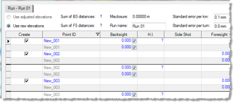
The Use raw elevations option is selected by default and cannot be changed for keyed-in level data.
- Select the number of station setups in the run.
- To change the name of the run, enter a new name in the Run name field at the top of the dialog.
- Optionally, change the standard error default values displayed in the Standard error per km and/or Standard error per turn fields:
- Standard error per km - This is the standard error on 1 km of double leveling. This value is typically published by the instrument manufacturer.
- Standard error per turn - This is the standard error for each station setup or turning point. This value is typically used when horizontal distances are not known.
These fields default to the values specified in Project Settings > Default Standard Errors > Leveling.
Note: You can specify different standard error values for each run. Although this is not commonly necessary, it can be helpful in some cases. For example, say run 1 was done on a windy day from benchmark A out to benchmark B. Run 2 was done on a calm day from benchmark B back to benchmark A through the same turning points. If these runs are then adjusted, it is reasonable to assume that run 2 should have a stronger influence on the adjustment than run 1. You can ensure this is the case by keying in smaller standard error values for run 2.
- To complete each of the displayed rows, do the following:
- Edit the default Point ID as necessary.
- Enter the Backsight or Foresight measurement value. (Optionally, remove the check mark to disable the measurement.)
The height of the instrument (HI) is computed from the raw elevation of the backsight plus the backsight rod reading; adjusting the run will not change the raw elevation so it will not change the height of the instrument.
- If the observation is to a benchmark, select Benchmark in the Elevation Type field and enter the elevation in the Adjusted Elevation field. If necessary, change the quality for the elevation.
If the elevation type is Computed, the elevation for the point is computed based on rod readings, benchmark, and coordinate elevations entered for the run, and any adjustments performed on the run.
Note: Another elevation type, Coordinate, is available only if the project contains a coordinate of the same name as the point before using the Level Editor.
- If known, enter a Distance for the observation.
The adjustment process always tries to use both distance-dependent and per-turn-dependent error estimates. However, when the Distance is left undefined or the Standard error per km value is not greater than zero, the weighting in the adjustment can use only the Standard error per turn value. If the Standard error per turn value is also zero, the adjustment uses a very high but not infinite weight.
- Optionally, enter information in the Description field.
The Description field can contain field notes or feature codes used to attach features to the resulting points in TBC (see step 9 below).
Misclosure is computed as you enter measurement values. The misclosure for the entire run is displayed at the top of the dialog in the Misclosure field. The misclosure for each benchmark is displayed in the Misclosure column.
- To add another station setup to the run, do the following:
- Select any observation in the setup after which you want to add the new station setup.
- Click the Insert Station Setup button located in the lower-right portion of the dialog (or right-click and select Insert Station Setup).
A new set of station setup rows is inserted following the selected station setup rows.
- To add a side shot to a station setup, do the following:
- Select any observation in the setup to which you want to add a side shot.
- Click the Insert Side Shot button located in the lower-right portion of the dialog (or right-click and select Insert Side Shot).
A new side shot row is inserted appropriately between the backsight and foresight rows in the station setup. If another side shot row already exists, the new side shot row is inserted after it.
- Enter the Side Shot measurement value. (Optionally, remove the check mark to disable the measurement.)
- If the side shot is to a benchmark, select select Benchmark in the Elevation Type field and enter the elevation in the Adjusted Elevation field. Then select the quality for the elevation.
- If known, enter a Distance for the observation.
This value is not used unless the side shot is to a benchmark.
- Optionally, enter information in the Description field.
The Description field can contain field notes or feature codes used to attach features to the resulting points in TBC (see step 9 below).
- In the Creation Options box in the lower section of the dialog, select one of the following options:
- Allow Network Adjustment - Select this option if you want all elevations of interest imported as delta elevations and, therefore, adjustable as part of a network adjustment.
- Prevent Further Adjustment - Select this option if you want all elevations of interest imported as control coordinates and, therefore, not adjustable as part of a network adjustment.
- In the Descriptions box in the lower section of the dialog, select one of the following options:
- Create Feature Codes - Select this option if the Description fields contain feature codes. The feature codes are displayed in the software for the selected observation and can be processed. You can edit feature codes directly in the Description column.
- Create Field Notes - Select this option if the Description field in the level data file contains field notes. The field notes are represented by nodes beneath the observations in the Project Explorer and can be viewed in the Properties pane. You can edit field notes directly in the Description column.
- Ignored - Select this option if you do not want to import data contained in the Description field.
- To add another run, do the following:
- Click the Add Run button located in the lower-right portion of the dialog.
- Complete the Create New Run dialog and click OK.
A new run tab is displayed in the Level Editor dialog.
- To merge multiple runs, see Merge Level Runs.
Notes:
- Merging runs does not affect the adjustment process however it can make runs easier to view.
- To merge two runs, the ending point ID in the selected Start With run must match the starting point ID in the selected Add This run. - To adjust one or more level runs to spread any misclosure proportionately through out all of the measurements, see Adjust Level Runs.
Note: When runs have points in common, the recommended procedure is to adjust them together.
- When you are done, click OK.
The level data is imported into your project.
You can now view keyed-in level data in the Project Explorer.
- To view complete information about the imported level data, including raw observations, reduced observations, and reduced coordinates, select Home > Reports > Level Report.
