Utility Node - Headwall Options
Use these options to define utility network objects such as pre-cast headwalls at pipe culverts. Count site improvements like these are represented by discrete markers, such as points or CAD points, but can also reference CAD blocks in graphic views.
When placed in your model, each headwall is automatically oriented to its associated utility line and is drawn and defined by a user-defined block for the Plan, Profile and 3D Views. Headwalls are primarily for gravity systems and have a single invert elevation. The headwall blocks supplied have a circular entrance at a scale of 1”. For a 24” pipe you can apply a scale of 24 to the headwall block and the entrance will have a diameter of 24”. The insertion point of the block will be placed at the XYZ location of the node. Headwalls also have a width setting that is used when defining the trench to allow for extra space around the headwall during construction. This width does not change with the scale.
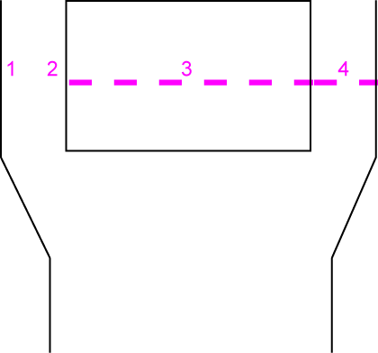
- Headwall width (specified for graphics in the associated block; specified below to control associated trench width)
- Headwall length (specified for graphics in the associated block)
- Invert elevation (specified when headwall objects are created in the model)
Figure: Headwall dimensions
If you have multiple pipes coming into a single headwall, you can position the line that centers on the structure to use the headwall and then use a “null” headwall for the remaining pipes. For a null headwall create, a block that draws just a point or line to indicate the end.
|
Options |
|
| Name |
This shows the descriptive name for the site improvement as it will appear in various commands that use utility nodes. These names should generally include size information to make object types easier to distinguish from each other. |
| Utility type |
Select a Type for the network you will use this node in; it will not appear as an option for other types of networks.
|
| Class |
Enter the industry type or rating of the headwall e.g., pressure or thickness. |
| Color |
Select a default display color for the headwalls as you want them to appear in graphic views. This can be changed in the properties for each object once they are created in your model. |
| Cost |
Enter the procurement cost of the headwall per unit. Note: This program displays the currency symbol and format that you have set in Microsoft Windows® Regional and Language Options. The units and calculations, however, are not associated with a specific currency, so if a project is opened on a computer with different regional settings, those currency symbol and formats are used, but no conversion between currencies has been made. |
| Plan View block |
Select a block to display at each headwall's location in the Plan View. If you do not have blocks in your project, see Import Block Definitions and Create a Block Definition. Note: It is recommended that a single headwall block be used to schematically model headwalls. The scale factor can be used to match the intended size so that the opening will match the intersecting pipe. A different block can be used in the Plan, Profile, and 3D Views. Simpler block are best in Plan View, and more realistic blocks are better in the 3D View. |
| Scale |
Select a factor by which to scale the inserted blocks in the Plan View. 1.0 = 100% of the block definition's original scale when it was imported or created. |
| Profile View block |
Select a 3D block to display at each headwall's location in the Profile View. Tip: You may want to name different versions of your blocks for their intended view, e.g., Headwall - Plan View, Headwall - 3D View. |
| Scale |
Select a factor by which to scale the inserted blocks in the Profile View. |
| 3D View block |
Select a 3D block to display at each headwall's location in the 3D View. |
| Scale |
Select a factor by which to scale (in X, Y, and Z) the inserted blocks in the 3D View. |
| Inspection criteria |
Inspection criteria is currently not implemented. |
| Width |
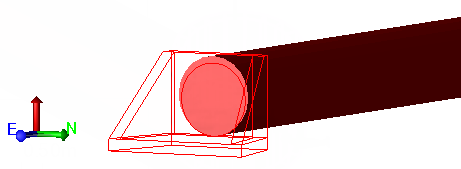
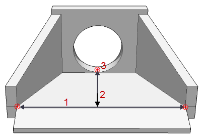
Specify the width dimension that affects how a trench surface is modified around the headwall when Adjust at nodes is enabled in an associated trench template.
Figure: Headwall width within a trench template |