Specify a Basic Trench Shape
Use the Basic tab in the Trench Template Manager to specify the basic, cross-sectional shape of a trench along utility lines and around utility nodes. You can also modify the specified settings for an existing trench line/trench node template. The shape can be confirmed in the dialog's preview pane.
As a trenching data manager, you can see a preview of the Basic settings that you have defined, so you can have an idea of how the trench will look like. The preview of the trench for which the Basic trench template settings are specified is displayed in the preview area and includes:
- Outline of primary utility line (outside and inside diameter) or node site improvement.
- Lines representing the bottom of the trench, and left and right sides.
- Dimension arrows for the bottom of the trench and the left side of the trench and offset from bottom.
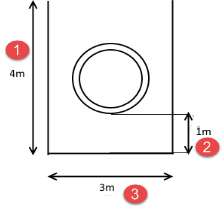
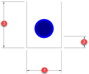
Figure: Preview of the trench for Basic settings
- The height from the bottom of the trench to the top is 4m.
- The distance from the bottom of the pipe to the bottom of the trench is 1m.
- The width of the trench from left to right is 3m; the width from bottom of the pipe to each side is 1.5m.
|
Basic tab options |
|
| Width method |
Choose how you want to specify the width of the trench. Then see the associated settings for each method below. As pipe sizes increase, the width will automatically increase.
|
|
Method - Total width
|
|
| Width |
Specify a total width for the trench (half of the width on each side of the center of the pipe). (1 above)
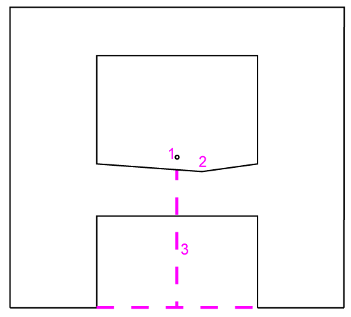
Figure: Height of user-defined shape Note: Typically, you need a minimum of 1m (36") trench width that includes 0.3m (1') clearance on each side. |
| Bottom offset |
Specify a depth for the trench bottom measured from the bottom of the pipe. (2 above) |
| Preview height |
Enter a height above the bottom of the trench to represent the hypothetical top of ground surface. (3 above) |
|
Node |
Adjust at nodes - Check this box to enable the settings below, which allow you to control the trench dimensions around utility nodes along a run. For each node, the side-to-side and front-to-back offsets is determined. A template that has the bottom offset and appropriate side offset is placed before and after each node. The type of utility node site improvement determines how the offsets are calculated:
Note: When you insert a template at a node, that template will be the driving template from that point on. |
|
|
Width offset - Specify a width for the trench on either side of a node. |
|
|
Bottom offset - Specify a depth for the trench bottom measured from the bottom of a node. |
|
Method - Side widths
|
|
| Measurement Location |
Select an option for the point from which the side widths are measured:
|
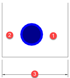
| Side width |
|
| Minimum width |
Specify the minimum width of the trench. If this value is more than the total of the left + right side widths, then the two side values are adjusted up (in proportion) to meet the minimum. (3 above) |
| Bottom offset |
See the description for the same setting above. |
| Preview height |
See the description for the same setting above. |
| Node |
See the description for the same settings above. |
|
Method - Diameter Multiplier
|
|
| Measurement Location |
See the description for the same setting above. |
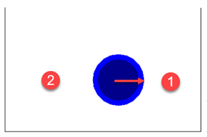
| Diameter multiplier |
Specify the factor by which to multiple the pipe's diameter (arrow above) to determine the left and right widths (1 and 2 above) of the trench. |
| Minimum width |
See the description for the same setting above. |
| Bottom offset |
See the description for the same setting above. |
| Preview height |
See the description for the same setting above. |
| Node |
See the description for the same settings above. |