Create a Best-Fit Line
Use the Best-Fit Line command to automatically create a straight or curved "best-fit" line based on the 2D or 3D survey, CAD, and/or scan points you select. This can be helpful, for example, when working with point clouds and creating curb and gutter linework.
Prerequisites:
- Points from which to create the line
To create a best-fit line
- Select Best-Fit Line in CAD > Lines to display the Best-Fit Line command.
- Click in the Selected field and then use the Project Explorer or a graphic view to select the points you want to use to create the best-fit line.
The number of points included in your selection is displayed in the Selected points field.
- In the Line type drop-down list, select the type of line you want to create:
- Straight Line 2D (Plan View) - Create a planimetric (no slope) line based on the points' X and Y values.
- Straight Line 3D - Create a sloping line (if the points have elevations) based on the points' X, Y, and Z- values.
- Polynomial Curve 2D (Plan View) - Create a planimetric (no slope) line based on the points' X and Y values, plus the specified polynomial degree.
- Polynomial Curve 3D - Create a sloping line (if the points have elevations) based on the points' X, Y, and Z- values, plus the specified polynomial degree.
- If you selected to create a polynomial curve, optionally change the Polynomial degree value.
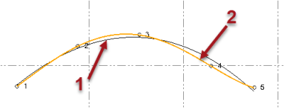
The following example shows two polynomial curves created using five points and two different Polynomial degree values: 1 = second degree (2); 2 = fourth degree (4). Note that in this case, only the fourth degree polynomial curve intersects all five points (5 - 1 = 4).
- Select a layer in the drop-down Layer list. Optionally, type any part of the layer name in the field. The function is case insensitive.
- If your project uses Custom fields, enter the required information under Custom Fields.
- Click Apply to create the line and keep the command pane open. Or, click OK to create the line and close the command pane.
