Specify Trench Backfill Materials
Once you have defined a cross-sectional trench shape (on the Basic and Side Slopes tabs), use the Backfill tab in the Trench Template Manager to specify backfill material layers for the template, generally filling up to a top of ground surface. You must enter the material layers in the correct order, from bottom to top, which can be confirmed using dialog's preview pane.
As a trenching data manager, you can see a preview of the backfill layers that you have defined, so you can visualize what the trench cross-section will look like. The preview of the trench, for which the Backfill settings of the trench template are specified, is displayed in the preview area and includes:
- All the material layers defined in the Backfill tab.
- A height dimension with the layer name graphic for each layer.
- Materials where the material areas are colored as per the material color.
Afterwards, you can run a Utility Takeoff Report to determine the volumes of the backfill materials. Like the Basic tab, values on the Backfill tab can be based on depths relative to the size of the utility line. The uppermost material is “Fill” and will be defined by the native material specified for the utility run.
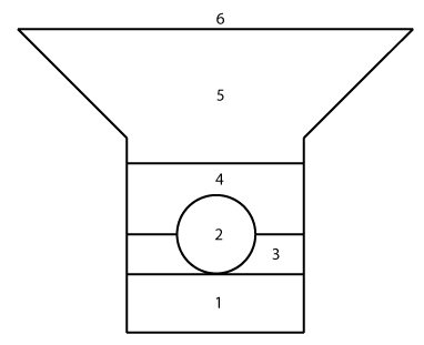
- Bedding
- Pipe (utility line)
- Initial backfill
- Additional backfill
- Fill
- Target surface (to which the template side slopes tie)
Figure: Cross-section view of typical utility trench backfill layers
For example:
- Specify the bedding material layer, which typically fills from the bottom of the trench up to bottom of the pipe. This can be done in multiple layers. For each layer, you would:
- Enter name: Bedding.
- Select from Fixed height, Percentage of diameter, or Relative height = Bottom of utility line.
- Specify the initial backfill layer, which fills from the bottom of pipe to pipe springline (or possibly higher). This is usually a single material layer.
- Enter name: Initial backfill.
- Select from Fixed height, Percentage of pipe diameter (specify inside or outside diameter), or Relative height = Centerline of utility line.
- Specify any additional backfill layers, which fills from the bottom backfill up to specified height above top of pipe, and may be done in multiple layers.
- Enter name: Backfill.
- Select from Top of layer is a specified height above top of pipe/node, top of inside or outside of pipe, or a thickness for each layer. Select Fixed thickness = 1.0 m.
- Specify the top fill layer, which fills from the top of the previous layer up to bottom of the target surface. This is typically a single layer.
- Enter name: Fill.
- Select Fill = 1.0 m.
To add backfill layers:
- Select an existing trench template for either a utility node or line. To create a new template, see Manage Trench Templates.
- In the Site improvement list, select the line object around which you will specify backfill in this template. The template displays in the preview pane.
- Click the Backfill tab.
- Click Add to specify a new layer or click Load Defaults to start with three default backfill material layers that you can modify.
- Select or edit the settings below and click Save.
|
Backfill Layer Properties |
|
| Name |
Enter a level name, such as bedding, initial backfill, backfill, or fill. |
|
Material |
The material of the pipe selected from the list. Note:For a Fill thickness type (see below), it is assumed that the site's native material (as specified in the Create Utility Run command) will be used for backfill, so <Native> appears and the list is disabled. |
|
Thickness type |
Select how you want to specify the thickness of the particular backfill layer.
|
To edit backfill layers:
- Select a material layer.
- Modify details in the fields, and click Save.
Options:
- Load Defaults - Select any new or existing trench line or trench node template name. The default backfill layers are displayed in the Backfill Layers table.
Note: You can modify the properties of default backfill layers.
- Delete - The selected backfill layer is deleted from the Backfill Layers table.
Note: You cannot delete default backfill layers.
