Create a Rectangle from Three Points
Use the Create Three-Point Rectangle command to create a rectangle by selecting three points and/or coordinates. Two points define the corners for one side of the rectangle; the third point defines where to draw the opposite side of the rectangle. This is especially useful when working with point clouds where you can use a limit box or cutting plane to specify a cross-section of an object (for example, a building facade) and then select three points to generate a rectangle within the view. This provides a useful alternative to the existing Create Rectangle command where you define a rectangle by specifying points for two opposite corners.
Prerequisites:
- None.
To access the command:
- Select Create Three-Point Rectangle in CAD > Lines.
To create a rectangle from three points:
- In the Create Three-Point Rectangle command pane, optionally enter a name for the new rectangle in the Name field.
A name is not required.
- Optionally, in the Layer drop-down list, select a different layer on which you want the rectangle to display, or select <<New Layer>> to create a new layer for the rectangle.
- Optionally, enter an elevation for the rectangle in the Elevation field.
This elevation will be applied to the entire rectangle regardless of elevations assigned to any existing points that might have been used to create the rectangle. If you do not enter an elevation, no elevation is assigned to the rectangle.
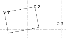
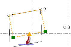
- Click in the Corner one field and then either type or select in a graphic view an existing point or a new coordinate for the first corner of the rectangle.
- Click in the Corner two field and then type or select a point or coordinate to define a corner adjacent to the first corner, forming a side of the rectangle.
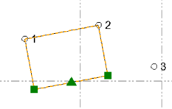
- Click in the Width field and do one of the following to define the width of the rectangle:
- Select a point or coordinate in the a graphic view.
- Right-click and select Offset at Point, enter the point ID in the Offset at Point command pane, and click OK.
- Type a distance value for the rectangle's width.
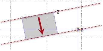
The following screen capture to illustrate how the width of the rectangle was computed based on the selected third point
- If your project uses Custom fields, enter the required information under Custom Fields.
- Click Apply.
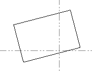
Lines are automatically drawn to form the rectangle's borders.
If you use coordinates instead of existing points to create the rectangle, no new points are created.
After the rectangle is created, you can delete or move any existing points, if they were used, without affecting the rectangle. Or, you can move or resize the rectangle as necessary using the rectangle's grips or its Properties pane.
Dependencies:
- None.
