Add Set Outs to a Tunnel
You can use the Edit Set Outs sub-tab on the Tunnel View tab to specify set out reference points at stations along the tunnel corridor, as described in this topic. Set out reference points can be used to assist in construction of the tunnel (for example, radial points and blast-hole points).
Set out points are used as follows:
- Radial - Commonly used to define rock bolt locations.
- Horizontal - Commonly used to define set out locations for anchors, rock bolts, and features on the tunnel wall.
- Vertical - Commonly used to define locations for anchors, rock bolts, and features on the tunnel ceiling/crown.
- Blast hole - Commonly used to define locations for drilling jumbo positioning and blasting locations.
- Pipe - Commonly used to define locations for pipe umbrella set outs. (A pipe umbrella system is a pre-support measure used in weak ground conditions in conventional as well as mechanized tunneling.)
Note: To include pipe set out properties in an exported tunnel design TXL file, be sure to use the latest version of the TXL exporter. The resulting TXL file cannot be imported into versions of TBC earlier than v5.80.
Note: Tunnel set outs are shown in the View Filter Manager, allowing you to toggle visibility for each of the five tunnel set out types on and off in 3D, Plan, Station, and other views.
You can view the tunnel design in 3D by selecting 3D View in Views > 3D View.
Prerequisites:
Licensed module. See the Subscription Plans page. For a license matrix by command, see the License page in the TBC Community. Also see View and manage licensed features.
This topic includes two subsections:
- "To add tunnel set out points individually"
- "To add multiple set out points at the same time"
To add tunnel set out points individually:
- Do either of the following to display the Set Outs sub-tab on the Tunnel View tab:
- Select Set Outs in Tunnels > Edit.
- If the Tunnel View tab is already displayed, select the Set Outs sub-tab.
- In the Tunnel drop-down list located in the lower-left portion of the tab, select the tunnel design for which you want to add set out points.
- Optionally, if a CSV (.csv) text file containing set out information from Trimble Access is available for import, click the Import button on the Set Outs sub-tab and select the CSV file you want to import.
The imported set out information is displayed on the Set Outs sub-tab. If necessary, you can proceed to the next step to edit any imported set out points or add new ones.
Note: The required format for the CSV file is: Start station, End station, Method, Hz offset, Vt offset, Code, Direction, Surface name, Center hz offset, Center vt offset. You cannot import multiple radial set out points.
- In the first row of the table, select the set-out Type and then edit any of the required and optional values as necessary.
- Use additional rows to specify additional set out points as necessary.
The following table identifies the required (Req), optional (Opt), and non-applicable (NA) values for each set-out type.
Type
Start Station
End Station
Horiz Offset
Vert Offset
End Horiz Offset
End Vert Offset
Horiz Center
Vert Center
Length
Direction
Shape Name
Code
Radial
Opt
Opt
Req
Req
NA
NA
Req
Req
NA
NA
Req
Opt
Horiz
Opt
Opt
NA
Req
NA
NA
NA
NA
NA
Req
Req
Opt
Vert
Opt
Opt
Req
NA
NA
NA
NA
NA
NA
Req
Req
Opt
Blast Hole
Opt
Opt
Req
Req
NA
NA
NA
NA
NA
NA
NA
Opt
Pipe
Opt
Opt
Req
Req
Req
Req
NA
NA
Req
NA
NA
Opt
Note the following:
- The Start Station and End Station fields are optional. If a station value is not entered, the first and/or last station of the tunnel alignment are used automatically by default.
- The Radial, Horizontal, and Vertical options enable you to specify offsets for set out points that are located on a tunnel shape segment.
- The Blast Hole and Pipe options enable you to specify offsets for set out points that are located anywhere inside or outside a tunnel's shape.
- The Pipe option also enables you to specify offsets for where the pipe ends that are different from where it begins, as determined by the Length distance.
- Horizontal and vertical offsets are relative to the alignment. If the alignment has been offset, the offsets are relative to the offset alignment.
The following example shows the various set-out options configured on the Edit Set Outs tab and the set-out symbols displayed on the Tunnel Viewtab.
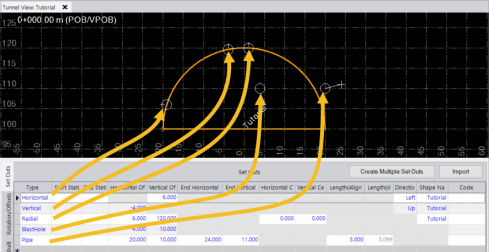
In the example, note that ending offsets specified for the the Pipe set out are different than the starting offsets. In this case, the symbols displayed include a hollow circle representing the starting offset for the Pipe set out, a plus sign representing the ending offset, and a connecting line.
To add multiple set out points at the same time:
The Set Outs tab in the Tunnel View includes a Create Multiple Set Outs button that opens a dialog allowing you to create a range of multiple set out points for a tunnel corridor design automatically, instead of creating each one individually using the Set Outs table. The dialog, which is easy and quick to use, allows you to specify all of the properties included in the Set Outs table for the selected set out points.
- Do either of the following to display the Set Outs sub-tab on the Tunnel View tab:
- Select Set Outs in Tunnels > Edit.
- If the Tunnel View tab is already displayed, select the Set Outs sub-tab.
- Click the Create Multiple Set Outs button to display the Create Multiple Set Outs dialog.
- In the Type drop-down list, select the method by which you want to add set outs to the tunnel design.
- Optionally, enter the Start Station and End Station to define the range of stations to which the set out points will be added.
If a station value is not entered, the first and/or last station of the tunnel are used automatically by default.
- Optionally, enter an identifier code to display for the new set out points.
The code is automatically appended with a dash and a unique incremented number for each set out point.
- Complete the remaining fields as necessary, depending on the set out type you selected in step 3.
- Radial - For this method, you will need to specify the starting and ending tunnel radial path length and the interval or fixed number of radial set out points to add along that path.
- Horizontal - For this method, you will need to specify the vertical height range and the interval or fixed number of horizontal set out points to add within that range.
- Vertical - For this method, you will need to specify the horizontal offset range and the interval or fixed number of vertical set out points to add within that range.
- Blast hole - For this method, you will need to specify the grid origin and the horizontal and vertical interval at which to add blast hole set out points.
- Pipe - For this method, you will need to specify the horizontal and vertical start and end set out points, the length of the pipes (distance between the start and end set out points along the tunnel alignment), the interval length at which to locate the set out points around the tunnel shape, the direction to arrange the set out points around the tunnel alignment, and the number of set out points to be created.
- When you are done, click OK.
The newly added set out points are displayed in the table on the Set Outs tab and in the Tunnel View (see "To add tunnel set out points individually" above.)
