Understanding Tunnels
You can import into your project a tunnel design created in Trimble Access and contained in a TXL (.txl) file. You can then, optionally, edit the tunnel design as necessary. You can also create a tunnel design directly in TBC that can be imported into Trimble Access or another TBC project.
A tunnel design is based on an alignment and corridor (to provide location and stationing) and defines the tunnel's shape (cross-section) geometry at each station of the tunnel along its entire length. This is accomplished by inserting tunnel shape templates, each specifying one or more tunnel shapes, at tunnel corridor stations as necessary, much the same as is done with templates in road corridors.
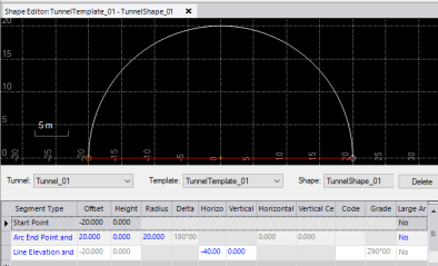
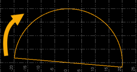
Following is an example of the instructions required to "draw" a simple tunnel shape in the Shape Editor in TBC.
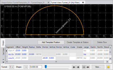
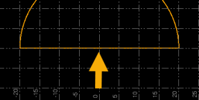
This next example shows a tunnel design being displayed in the Tunnel View, where you can use the slider/navigation controls to view the shape of the tunnel at any station along the tunnel corridor
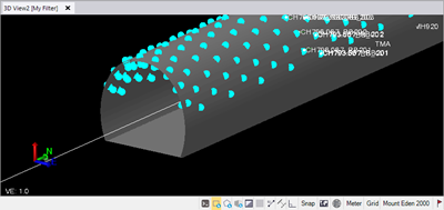
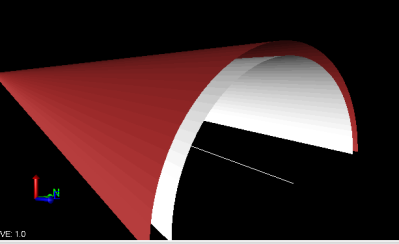
The following example shows a 3D view of a tunnel design. You can view the 3D design by selecting 3D View in Views > 3D View.
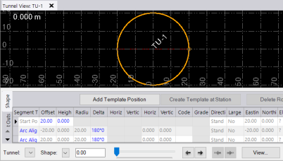
The following example shows a vertical shaft tunnel design. Vertical shafts are common in tunnel and underground mining construction to allow construction or extraction to be started at lower depths.
Once you have imported or created a tunnel design, you can edit it by doing any of the following:
- Apply rotation to the tunnel at one or more stations along the tunnel corridor.
- Apply a horizontal and/or vertical offset from the tunnel alignment centerline at one or more stations along the tunnel corridor.
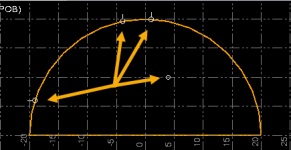
- Specify set out reference points at one or more stations along the tunnel corridor that can be used to assist in the construction of the tunnel (for example, radial points and blast-hole points).
You can create a designed tunnel mesh surface as a visual aid in viewing the shape of the tunnel design in the 3D View, where you can view the tunnel from various perspectives and use the Walk-Through Viewand 3D Drive Viewto further explore the interior and exterior of the tunnel.
Once your tunnel design is complete, you can import as-built points to compare to the tunnel design to determine overbreak and underbreak information that can be displayed in predefined and customizable tunneling reports and cross-section drafting sheet sets. In addition, you can create a number of other types of tunneling reports for quality checking and communications.
In the following example, tunnel as-built overbreak and underbreak are shown relative to the designed surface shape.
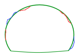
- Green = designed, cross-sectional tunnel shape
- Blue = as-built overbreak beyond the desired shape
- Red = as-built underbreak inside the desired shape
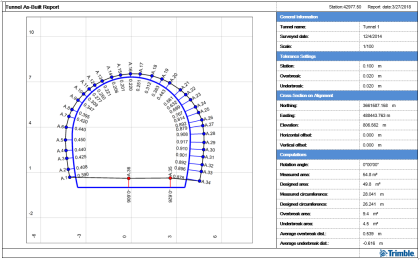
Following is an example of the Tunnel As-Built Report.
See Tunnel Workflows for high-level step-by-step instructions, along with links to more specific task details.
Note: To view a table showing which Tunnel commands are applicable to each of the two primary tunnel types (horizontal and vertical shaft),  click here.
