Create a Designed Tunnel Mesh
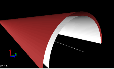
Optionally, use the Create Designed Tunnel Mesh command to create a 3D tunnel mesh as a visual aid in viewing the shape of a tunnel design in the 3D View, where you can view the tunnel from various perspectives. The 3D mesh also allows you to use the Walk-Through Viewand 3D Drive View to further explore the interior and exterior of the tunnel and capture a "slice" of the tunnel in the Cutting Plan View. In addition, designed tunnel meshes can be exported to DWG files.
Notes:
- A 3D mesh is the structural build of a 3D model consisting of polygons. 3D meshes use reference points in X, Y, and Z axes to define shapes with height, width, and depth.
- DWG files created from exported designed tunnel meshes cannot be imported back into TBC.
Note the following restrictions when using the Create Designed Tunnel Mesh command:
- You cannot specify a designed tunnel mesh as a target surface on commands targeting surfaces (for example, the Drape Objects command, Surface Vertex snap, and others.
- Designed tunnel meshes do not display in the Cross-Section View and Surface Slicer View.
Prerequisites:
- Licensed module. See the Subscription Plans page. For a license matrix by command, see the License page in the TBC Community. Also see View and manage licensed features.
- Tunnel (created or imported as tunnel design data (.txl))
To create a designed tunnel mesh:
- Select Create Designed Tunnel Mesh in Tunnels > View to display the Create Designed Tunnel Mesh command pane.
- Enter a Name for the new designed tunnel mesh.
- Select the Tunnel and Tunnel shape for which you want to create a tunnel mesh.
- Select a layer in the drop-down Layer list. Optionally, type any part of the layer name in the field. The function is case insensitive.
- Select a Color for the tunnel mesh.
- Click Apply if you want to create additional designed tunnel meshes, or click OK if you are done.
A new Designed Tunnel Mesh node displays in the Project Explorer, nested beneath the selected tunnel.
- To view the designed tunnel mesh on the 3D View tab, select 3D View in Views > 3D View.
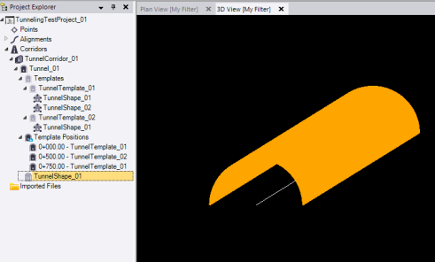
The following example shows a horizontal tunnel mesh.
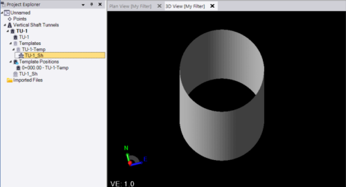
This next example shows a vertical shaft tunnel mesh.
Optionally, use the Walk-Through View and 3D Drive View commands to further explore the tunnel design.
- To view information about a designed tunnel mesh and/or edit its appearance (for example, hide or show wireframes, vertices, and edges), right-click its node in the Project Explorer and select Properties.
Note the following:
- A tool tip is displayed for each property when you select it that explains its use.
- To view the volume of the designed tunnel mesh, in the Volume Information group enter a Station interval at which you want volumes to be computed along the entire length of the tunnel's alignment. (Stations created for tunnel shape changes are automatically used to create intervals that are ncluded in the computation.) The starting and ending mesh cross-sections for each station interval are averaged and multiplied by the station interval length to compute the volume for that interval. After the volume for each station interval is computed, all interval volume totals are combined to provide the value displayed in the Total volume field.
If there are no mesh shape changes along the entire length of the tunnel alignment, you could just enter the total length as the Station interval. If there are mesh shape changes along the alignment, you might want to enter a shorter Station interval to more accurately capture changes that impact the volume of the mesh.
Optionally, you can compare the Total volume displayed in the Designed Tunnel Mesh Properties pane with the Total volume displayed in the As-Built Tunnel Mesh Properties pane to identify differences.
- To delete a designed tunnel mesh, right-click its node in the Project Explorer and select Delete.
- To toggle between displaying and hiding a designed tunnel mesh, right-click its node in the Project Explorer and select Toggle Visibility. Or, use the View Manager.
