Create a Vertical Shaft Tunnel Design
Use the Create Vertical Shaft Tunnel command to create a vertical shaft tunnel design. Vertical shafts are common in tunnel and underground mining construction to allow construction or extraction to be started at lower depths.
You will start by defining the vertical shaft alignment based on a specified top coordinate, a depth, and rotation around the z-axis as described in this topic. The following diagram shows an example of a vertical shaft tunnel design and the elements that define it.
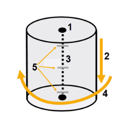
1. Top coordinate: Easting, Northing, Elevation
2. Tunnel depth
3. Vertical tunnel alignment (based on top coordinate and depth)
4. Rotation around the Z axis
5. Station interval
After defining the vertical shaft alignment, you can then define the vertical-shaft tunnel shape (geometry), and create a design mesh to visualize the tunnel in the 3D View and Tunnel View. Finally, you can create a Tunnel Inspection Map that compares the design tunnel mesh to an as-built tunnel mesh (or two as-built tunnel meshes) and create a Tunnel As-Built Report, just as you can do with horizontal tunnels. This allows for construction quality control and verification of vertical shafts using point cloud or total station data to ensure and document that tolerances were met for excavation, foundation lining, and as-built processes.
Note: To view a table showing which Tunnel commands are applicable to each of the two primary tunnel types (horizontal and vertical shaft),  click here.
Preequisites:
Licensed module. See the Subscription Plans page. For a license matrix by command, see the License page in the TBC Community. Also see View and manage licensed features.
To create a tunnel design:
- Select Create Vertical Shaft Tunnel in Tunnels > Create to display the Create Vertical Shaft Tunnel command pane.
- Enter a Name for the new tunnel design
- Select the Layer on which to display the tunnel.
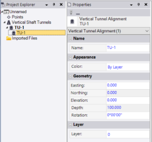
- Click in the Easting field and select a coordinate for the location of the tunnel in the Plan View. Or, type in the Easting and Northing coordinates.
- Enter the Elevation for the start of the tunnel.
- Enter the Depth of the tunnel.
- In the Rotation field, enter the degrees of rotation of the tunnel around the Z axis.
- Specify the Station Interval, which is used to determine the increments used with the video controls when you view a tunnel in the Tunnel View.
- Click the Apply or OK button (closes the command pane) to save the new tunnel design in your project.
The new tunnel is represented by a new Vertical Shaft Tunnel node in the Project Explorer.
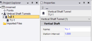
Nested beneath it is a Vertical Tunnel Alignment node.
- Create one or more templates used to apply tunnel shapes in the new tunnel (see Create a Tunnel Shape Template).
- Create one or more tunnel shapes to apply to the tunnel using tunnel shape templates (see Create a Tunnel Shape).
- Apply one or more tunnel templates to specific tunnel corridor stations, in addition to the station specified when you created each (see Add a Tunnel Shape Template Position).
- Optionally, view and edit the properties and changes in the cross-sectional shape of a tunnel design along its entire length (see View Tunnel Designs).
- Optionally, create a design mesh to visualize the tunnel in the 3D View and Tunnel View (see Create a Designed Tunnel Mesh).
- Optionally, create a Tunnel Inspection Map that compares the design tunnel mesh to an as-built tunnel mesh (see Create a Tunnel Inspection Map) and create a Tunnel As-Built Report (see Run a Tunnel Inspection Report).
This allows for construction quality control and verification of vertical shafts using point cloud or total station data to ensure and document that tolerances were met for excavation, foundation lining, and as-built processes
